Performance Tests
TDS 684A, TDS 744A, & TDS 784A Service Manual
4–73
COMPST on the TSG 121) to a 75 W cable and a 75 W terminator.
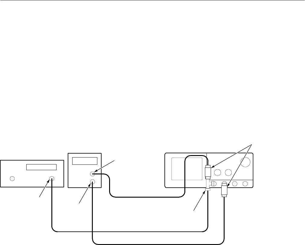
Connect both signals to the CH1 input through a BNC T. See
Figure 4–32.
H Press VERTICAL MENU.
H If needed, press the main-menu Fine Scale.
H Use the keypad to set fine scale to 500 mV (press 500, SHIFT, m,
then ENTER).
H Connect another composite signal connector of the PAL signal
source (labeled COMPST on the TSG 121) through a 75 W cable
and a 75 W terminator to the CH2 input. See Figure 4–32.
PAL Signal
Source
BNC T
Connector
75 W
Terminators
Digitizing Oscilloscope
50 W Cable
Signal Generator
75 W Cable
75 W Cable
COMPST
COMPST
Output
Figure 4–32: Subsequent 60 Hz Rejection Test Hookup
H CONFIRM that the TRIG’D LED stays lighted and that the
waveform on screen is stable. In other words, be sure the waveform
does not move horizontally or vertically. Also, confirm that the
waveform on the screen has one positive pulse and a number of
negative pulses. See Figure 4–33.
H Disconnect all test equipment from the digitizing oscilloscope.


