


Brief Procedures
TDS 684A, TDS 744A, & TDS 784A Service Manual
4–13
H Verify that the trigger READY indicator on the front panel flashes
about once every second as the waveform is updated on-screen.
4. Remove the test hookup: Disconnect the probe from the channel input and
the probe-compensation terminals.
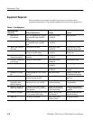
Equipment
Required
One probe such as the P6245 or P6139A
One 720 K or 1.44 Mbyte, 3.5 inch DOS-compatible disk.
You can use a disk of your own or you can use the Programming
Examples Software 3.5 inch disk (Tektronix part number 063-1134-XX)
contained in the TDS Family Programmer Manual (Tektronix part
number 070-8709-XX).
Prerequisites None
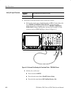
1. Install the test hookup and preset the oscilloscope controls:
a. Hook up the signal source: Install the probe on CH 1. Connect the probe
tip to PROBE COMPENSATION SIGNAL on the front panel;
connect the probe ground to PROBE COMPENSATION GND. See
Figure 4–3 on page 4–8.
b. Insert the test disk: Insert the disk in the disk drive to the left of the
monitor.
H Position the disk so the metal shutter faces the drive.
H Position the disk so the stamped arrow is on the top right side. In
other words, place the angled corner in the front bottom location.
H Push the disk into the drive until it goes all the way in and clicks
into place.
c. Initialize the oscilloscope:
H Press save/recall SETUP.
H Press the main-menu button Recall Factory Setup.
H Press the side-menu button OK Confirm Factory Init.
d. Modify default settings:
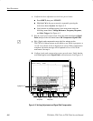
H Set the vertical SCALE to 200 mV.
H Set the horizontal SCALE for the M (main) time base to 200 ms.
Notice the waveform on the display now shows two cycles instead of
five.
H Press CLEAR MENU to remove the menus from the screen.
Verify the File System