


Removal and Installation Procedures
TDS 684A, TDS 744A, & TDS 784A Service Manual
6–37
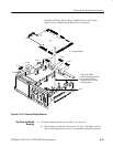
installed, A29 Video Trigger Board, and Rear Cover and Cabinet
(page 6–18) to complete reassembly of the oscilloscope.
J62
J38
J35
J51
J37
J2
J5
J20
To J5
To J37
To J51
To J2
J2
J37
J51
J5
J38
J38
To J38
To J20
J20
To J38
To J62
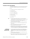
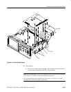
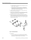
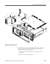
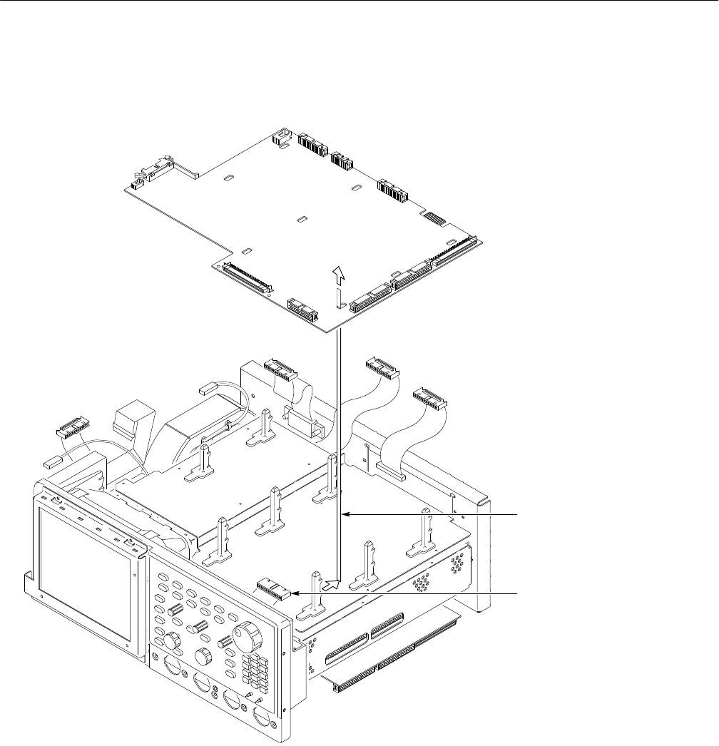
Slide the A11 DRAM
Processor/Display board to the
rear to release it from the
board mounts; then lift up to
complete removal.
2
Unplug the cables.
1
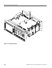
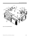
Figure 6–16: A11 Processor/Display Removal
1. Assemble equipment and locate modules to be removed:
a. Have handy a screwdriver with a size T-15 TorxR tip (Items 1 and 2)
and, if removing any board mount, a flat-bladed screwdriver (Item 5).
Top Cover and Board
Brackets