Removal and Installation Procedures
6–22
TDS 684A, TDS 744A, & TDS 784A Service Manual
1. Assemble equipment and locate modules to be removed: No tools are needed.
Locate the modules to be removed in the locator diagram External Modules,
Figure 6–1.
2. Orient the oscilloscope: Set the oscilloscope so its rear is down on the work
surface and its bottom is facing you.
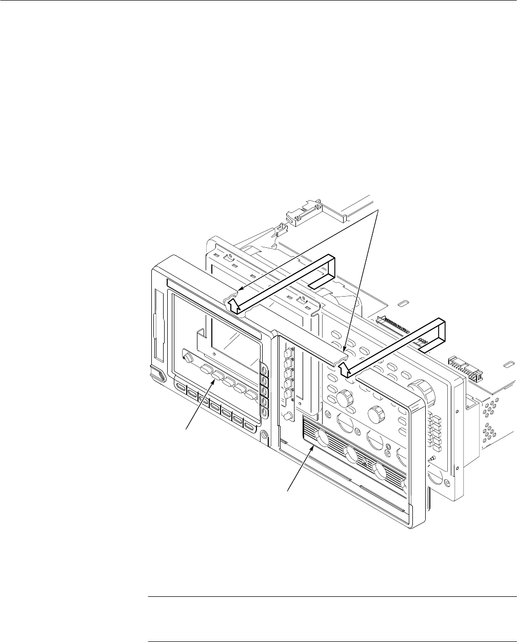
3. Remove the front cover: Grasp the front cover by its left and right edges and
snap it off of the front subpanel. When reinstalling, align and snap back on.
See Figure 6–7.
Attenuator Panel
Menu Buttons
Trim Ring. When removing the
trim ring, grasp its back edge
and vigorously flex it upward
before pulling it forward.
Figure 6–7: Front Cover, Trim Ring, Menu Buttons, and Attenuator Panel Removal
(Front Cover not Shown)
STOP. DO NOT touch the carbon contact points on the menu buttons installed in
the trim ring. Also, do not touch the contacts on the flex circuit exposed when
you remove the trim ring.
Front Cover, Trim Ring,
Menu Buttons, and
Attenuator Panel
