Adjustment Procedures
TDS 684A, TDS 744A, & TDS 784A Service Manual
5–9
d. Follow the instructions as prompted on your computer screen. This will
include the actions listed in step 5 shown below.
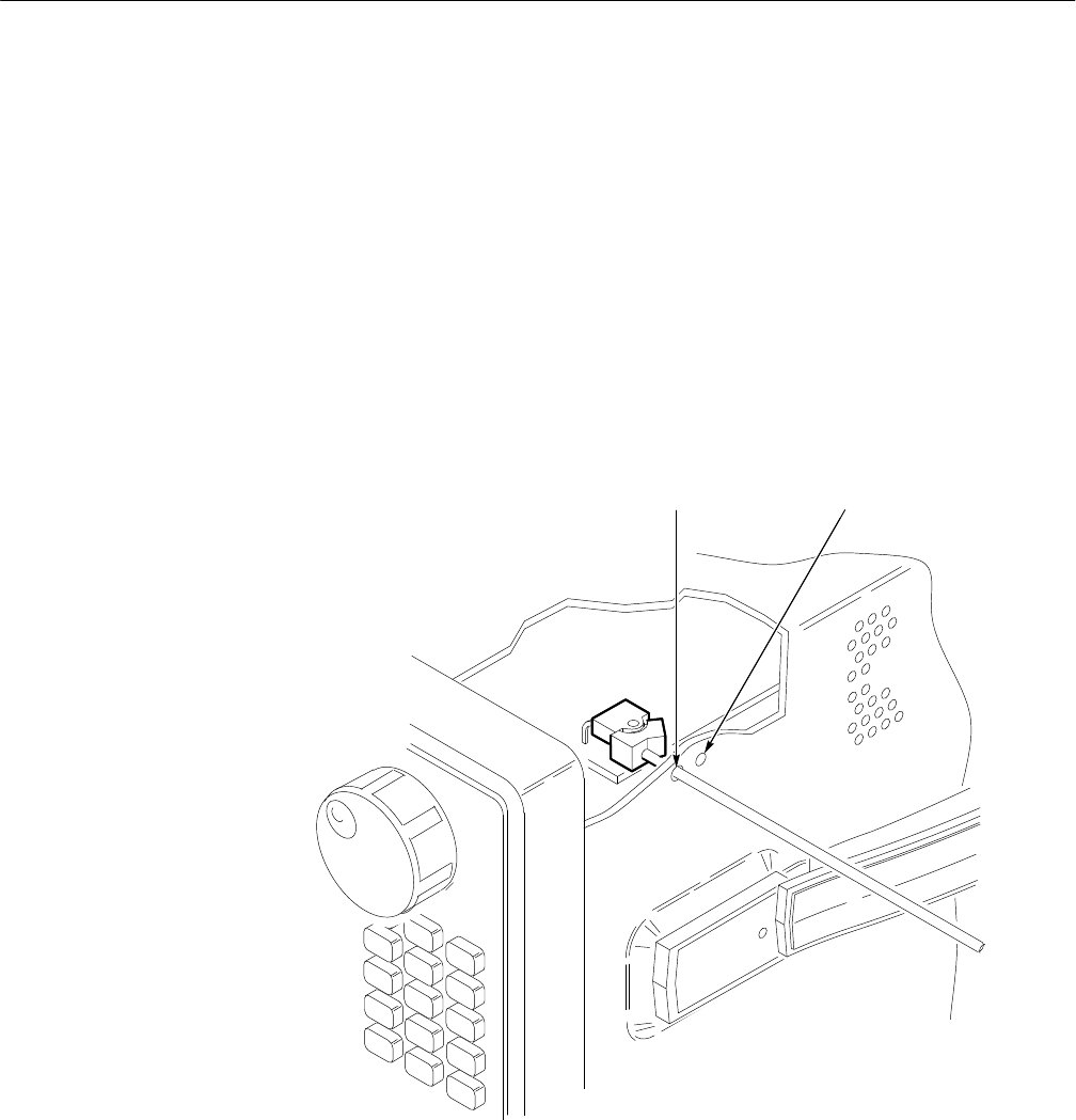
5. Enable the adjustment constants to be written –when prompted on your
computer screen in step 4 above:
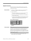
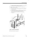
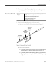
a. Locate the two small access holes on the right side of the oscilloscope
cabinet near the front.
b. Insert the adjustment tool (Item 3) in the hole nearest the front of the
oscilloscope about 1/2 inch to engage the rocker switch.
c. Push to rock the switch to its unprotected (enabled) position.
See Figure 5–1.
Unprotected
Protected
Figure 5–1: Accessing the Protection Switch
6. When adjustment has been completed:


