Removal and Installation Procedures
6–16
TDS 684A, TDS 744A, & TDS 784A Service Manual
c. Do, in the order listed, the three procedures A14 D1 Bus and Analog-
Power and Digital-Power Cables, A11 Processor/Display Board and Top
Cover found under Procedures for Outer-Chassis Modules, page 6–29.
d. Find and do the procedure whose title matches the name of the module
to be removed under Procedures for Inner-Chassis Modules, page 6–46.
6. Reinstall all modules removed: Read the instructions found at the end of the
procedure that removes the module to be serviced — they will guide you in
reinstalling all modules removed.
Procedures for External Modules
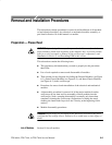
Do the Access Procedure (page 6–15) before doing any procedure in this
collection.
The following procedures are found here and are listed in order presented.
H Front-Panel Knobs
H Line Fuse and Line Cord
H EMI Gaskets
H Rear Cover and Cabinet
H Front Cover, Trim Ring, Menu Buttons, and Attenuator Panel
H A12 Front-Panel Assembly
H Display Frame Assembly
H Cabinet Modules
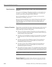
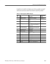
1. Assemble equipment and locate modules to be removed: Have an angled-tip
tweezers
(Item 9) handy. Find the knob(s) to be removed on the front panel.
2. Orient the oscilloscope: Set the oscilloscope so its bottom is down on the
work surface and its front is facing you.
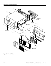
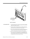
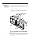
3. Remove the knob(s): Grasp any knob you wish to remove and pull it straight
out from the front panel slightly to create some clearance between the base
of the knob and the front panel. Insert the tweezers between the knob and
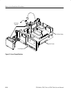
front panel and use them to remove the knob. See Figure 6–4.
4. Reinstallation: To reinstall, align knob to shaft and push it in until it snaps.
Front-Panel Knobs


