TDS 684A, TDS 744A, & TDS 784A Service Manual
3–1
Theory of Operation
This section describes the electrical operation of the TDS 684A and 7XXA Digi-
tizing Oscilloscopes using the major circuit blocks or modules.
This section has two main parts:
H Logic Conventions describes how logic functions are discussed and
represented in this manual.
H Module Overview describes circuit operation from a functional-circuit block
perspective.
Logic Conventions
The Digitizing Oscilloscopes contain many digital logic circuits. This manual
refers to these circuits with standard logic symbols and terms. Unless otherwise
stated, all logic functions are described using the positive-logic convention: the
more positive of the two logic levels is the high (1) state, and the more negative
level is the low (0) state. Signal states may also be described as “true” meaning
their active state or “false” meaning their nonactive state. The specific voltages
that constitute a high or low state vary among the electronic devices.
Active-low signals are indicated by a tilde prefixed to the signal name
(~RESET). Signal names are considered to be either active-high, active-low, or
to have both active-high and active-low states.
Module Overview
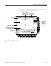
This module overview describes the basic operation of each functional circuit
block as shown in Figure 9-2.
The TDS 684A and 7XXA Digitizing Oscilloscopes have four channels. Each
channel provides a calibrated vertical scale factor.
A signal enters the oscilloscope through a probe connected to a BNC on the A10
Attenuator/Acquisition board.
Attenuators. Circuitry in the attenuator selects the input coupling, termination,
and the attenuation factor. The processor system, by way of the acquisition
system, controls the attenuators. For example, if 50 W input termination is
General
Input Signal Path


