


Removal and Installation Procedures
6–44
TDS 684A, TDS 744A, & TDS 784A Service Manual
1. Assemble equipment and locate modules to be removed:
a. Have handy a screwdriver with a size T-15 TorxR
tip (Items 1 and 2).
b. Locate the modules to be removed, including those listed under
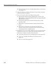
Additional Modules Removed in the locator diagram Outer-Chassis
Modules, Figure 6–2, page 6–13.
c. Install the front cover if it’s not already installed.
2. Orient the oscilloscope: Set the oscilloscope so its bottom is down on the
work surface and its rear is facing you.
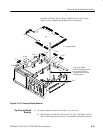
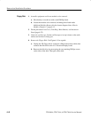
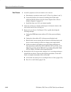
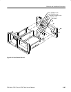
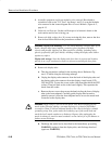
3. Remove the rear chassis: Use Figure 6–20 as a guide when doing the
following substeps:
a. Unplug the GPIB interconnect cable at J35 of the processor/display
board.
b. Unplug the video cable at J51 of the processor/display board.
c. Remove the 6 screws securing the rear chassis to the main chassis and
the two screws securing it to the low-voltage power-supply shield.
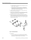
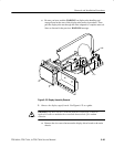
d. Lift the rear chassis up slightly to access the cables connected to it.
Disconnect those cables from (CH 3) SIGNAL OUT (at J1201), AUX
TRIG IN (at J1550), MAIN TRIG OUT (at J1000), DELAYED TRIG
OUT (at J1001), all found on the acquisition board.
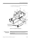
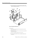
4. Reinstallation: Do, in reverse order, substeps 3a–3c, reversing each step to
reinstall the rear chassis. Then see the following procedures, in the order
listed, to complete reassembly of the oscilloscope.
H A14 D1 Bus and Analog-Power and Digital-Power Cables (page 6–29)
H Rear Cover and Cabinet (page 6–18)
Rear Chassis