


Removal and Installation Procedures
TDS 684A, TDS 744A, & TDS 784A Service Manual
6–25
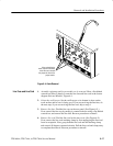
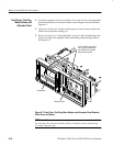
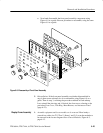
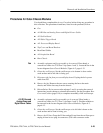
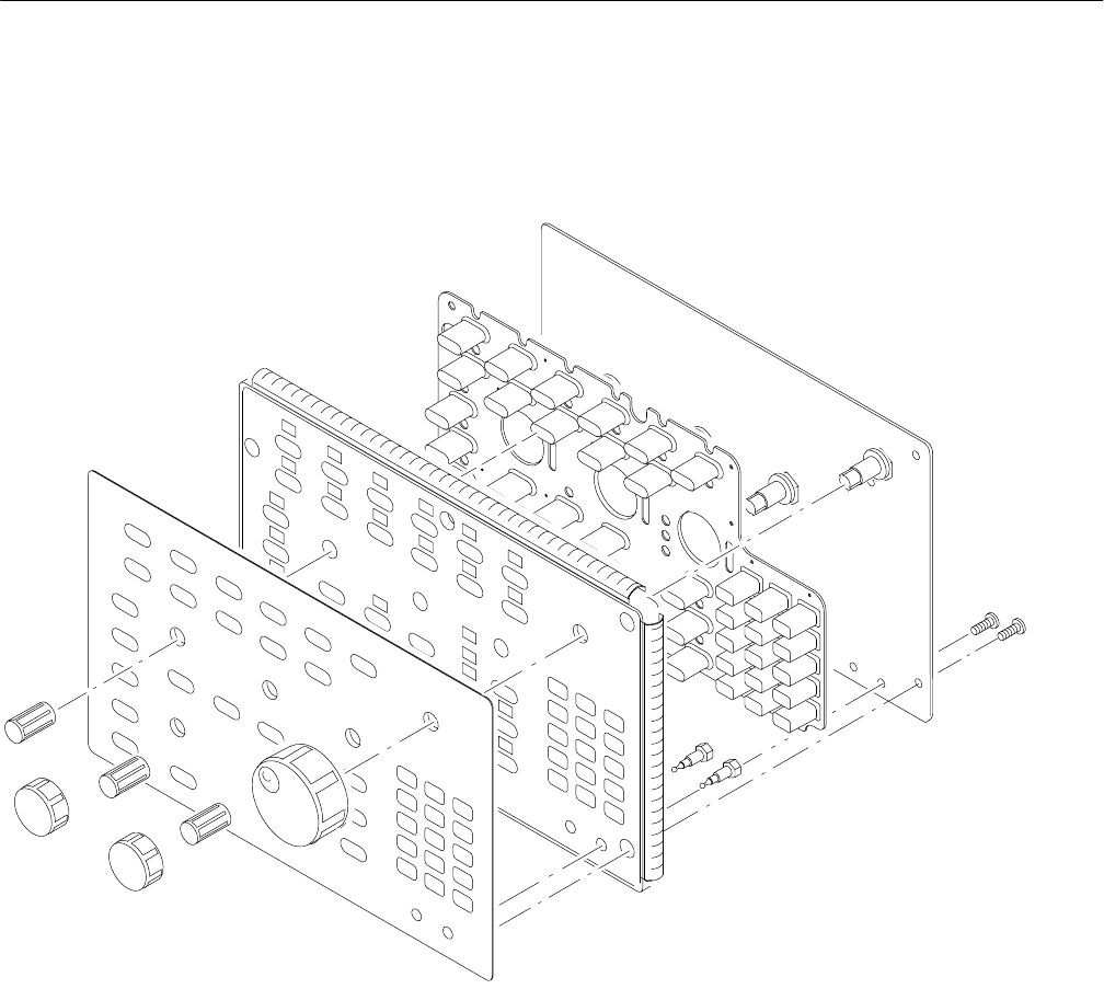
c. Now hand disassemble the front-panel assembly components using
Figure 6–9 as a guide. Reverse procedure to reassemble, using the same
Figure 6–9 as a guide.
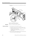
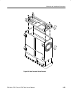
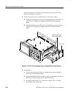
Figure 6–9: Disassembly of Front-Panel Assembly
5. Reinstallation: If the front-panel assembly was further disassembled in
step 4, then reverse substeps 4a–4c to reassemble, using Figure 6–9 as a
guide. Then do step 3, reversing the procedure outlined in each substep.
Last, reinstall the trim ring and, if desired, the front cover, referring to the
procedure Front Cover, Trim Ring, Menu Buttons, and Attenuator Panel
(page 6–22).
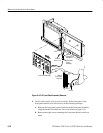
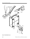
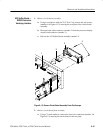
1. Assemble equipment and locate modules to be removed: Have handy a
screwdriver with a size T-15 TorxR
(Items 1 and 2). Locate the modules to
be removed in the locator diagram Outer-Chassis Modules, Figure 6–2,
page 6–13.
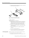
Display-Frame Assembly