Telect, Inc. • USA +1.509.926.6000 • Mexico +1.52.33.3836.3700
Poland +1.48.713.239.100 • UK +1.44.1489.889500 • www.telect.com
Copyright © 2002 Telect, Inc., All Rights Reserved
Page 2-8
— C. Install Intrabay & Interbay Cabling
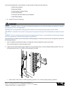
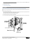
The input -48 and RTN plates contain mounting holes for bus extensions to other panels in the same bay. Telect has busing and ca-
bling kits for all types of input extensions.
— D. Install Alarm Cabling
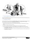
External indicators (monitors) can be connected to the BDFB / BDCBB alarm board. The external indicators can be wired to accept
either a normally open or closed circuit when the VDC PWR or FUSE ALM LEDs or other optional alarms are activated.
To connect power- and fuse-alarm circuits to the BDFB / BDCBB, proceed as follows:
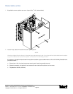
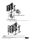
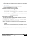
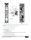
1. Refer to the following illustration and then remove four Phillips screws (screws with cross-recessed heads) securing alarm
panel.
2. Carefully pull off and turn alarm panel cover around.
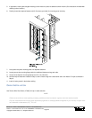
3. Strip off ¼ in. of insulation on end of a pair of 18-24 AWG alarm wires for each external alarm circuit desired.
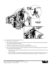
4. Select a common (C) contact and either a normally closed (NC) or normally open (NO) contact for each alarm desired:
• For a C and NC pair, expect continuity (0 Ω) during normal operation and an open circuit (∞ Ω) for an alarm condition such
as an open breaker or a power failure.
•For C and NO pair, expect an open circuit (∞ Ω) during normal operation and continuity (0 Ω) for an alarm condition such as
an open breaker or a power failure.


