Telect, Inc. • USA +1.509.926.6000 • Mexico +1.52.33.3836.3700
Poland +1.48.713.239.100 • UK +1.44.1489.889500 • www.telect.com
Copyright © 2002 Telect, Inc., All Rights Reserved
Page 2-10
With Feed A power OK and without any installed circuit breakers, expect either continuity (0 Ω) between C and NC poles and/or
an open circuit (∞ Ω) between C and NO.
5. Repeat procedure for Feed B.
— F. Install Output Cabling
ALERT
!
ALERT! Feeds A and B may be powered. Use voltmeter to verify, and then proceed accordingly.
Remember to finish all input cabling (including all intrabay and interbay input cabling) before proceeding with output cabling in that
bay.
Proceed as follows to cable panel outputs:
1. Use a UL-approved crimping tool to attach UL-approved, dual-hole compression lugs onto each pair of copper output and return
cables (up to #2 AWG), as required by NEC. Insulate lug barrels as required.
Size of cables is determined by size of breaker intended for that cable.
2. Clean terminals and lugs with a nonabrasive, nonmetallic pad.
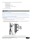
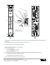
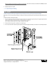
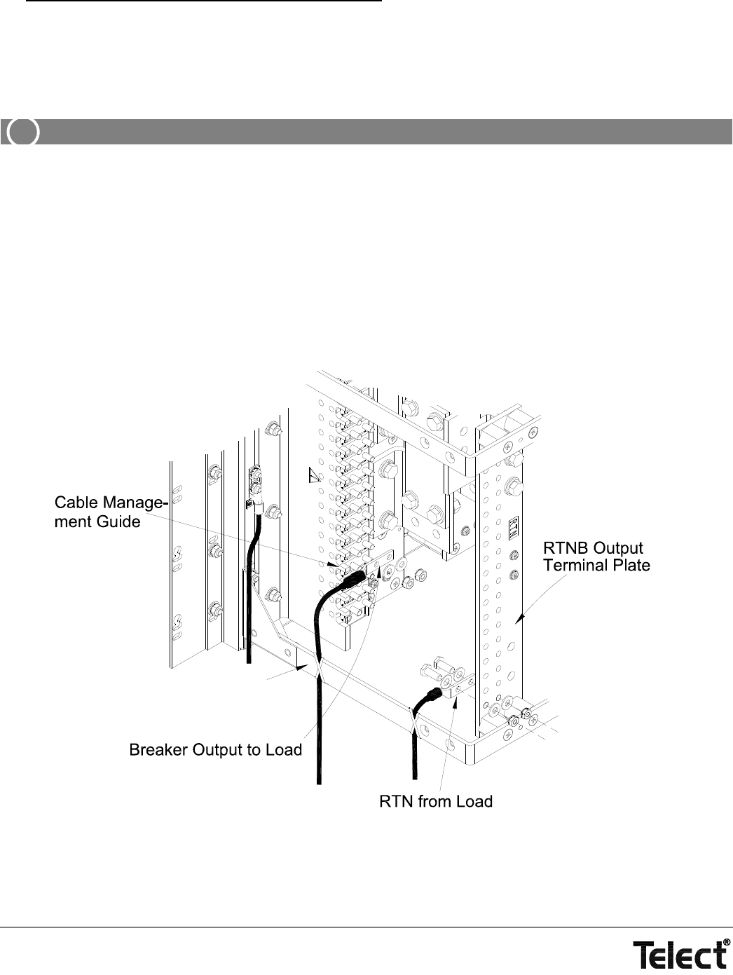
3. Plan to route and restrain cables along the outside of the cable management brackets, as indicated in the following illustration.
Cable Management Bracket


