Telect, Inc. • USA +1.509.926.6000 • Mexico +1.52.33.3836.3700
Poland +1.48.713.239.100 • UK +1.44.1489.889500 • www.telect.com
Copyright © 2002 Telect, Inc., All Rights Reserved
Page 1-5
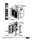
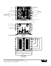
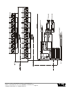
Side B
4.00
(10.16)
(44.37)
17.47
14.00
(35.56)
(27.94)
11.00
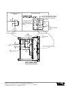
(1 of 2 Provided)
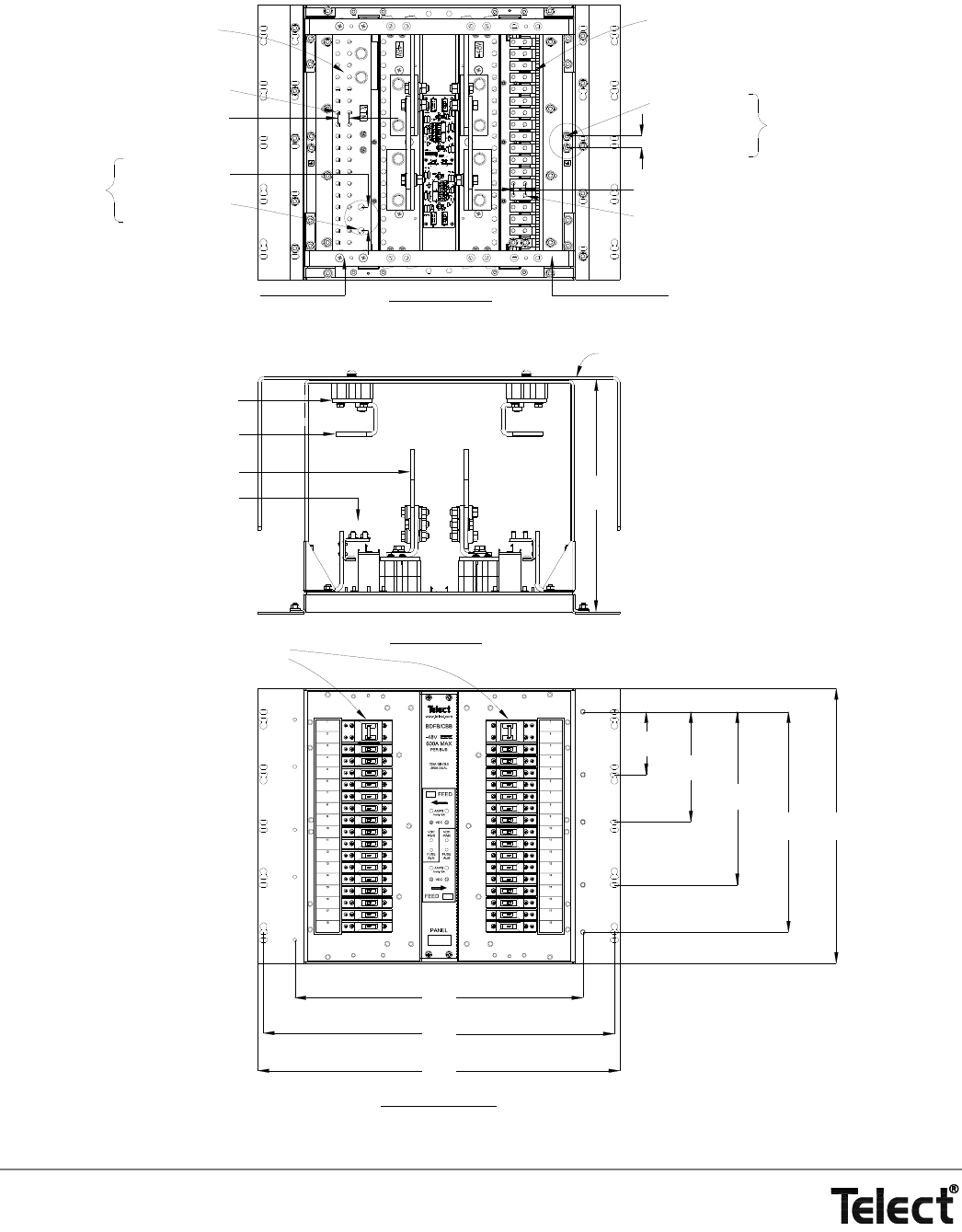
Connections
Ground
Optional Rear Cover
(Panel is Shipped Without Breakers.)
Normal Breaker Layout is Shown Here.
RTN B Outputs
}
(1.03)
(ROTATED AND SHOWN WITHOUT
OPTIONAL COVER AND RTN A BUS)
REAR VIEW
}
Side A Breaker Outputs
1/4-20 Stud & KEPS
.750
(1.90)
Center Spacing
for Viewing Breaker
1/4-20 Stud & KEPS
Center Spacing
(1.90)
.750
Outputs
RTN A Bus Removed
Alarm
Board
Hole Dia.
Center Spacing
RTN B Bus
Center Spacing
Hole Dia.
Connection Provided
for Strapping Input
RTN to an Extension
Panel
(1.90)
(3.81)
1.50
.406
.750
.266
(.676)
RTN A Output Terminal Plate
RTN A Input Terminal Plate
-48 A Input Terminal Plate
Side A Breaker Outputs
}
(37.46)
14.75
FRONT VIEW
TOP VIEW
(46.51)
(56.67)
(58.42)
18.31
22.31
23.00
Side A
(17.78)
7.00


