Telect, Inc. • USA +1.509.926.6000 • Mexico +1.52.33.3836.3700
Poland +1.48.713.239.100 • UK +1.44.1489.889500 • www.telect.com
Copyright © 2002 Telect, Inc., All Rights Reserved
Page 2-9
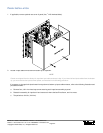
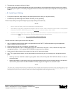
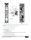
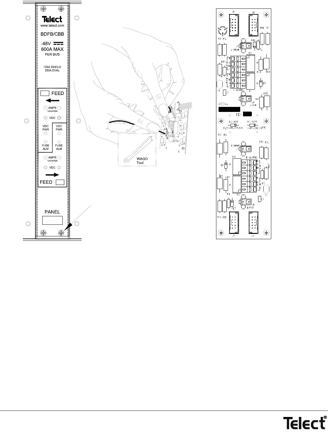
5. For each contact, insert WAGO tool (supplied) into connector to release contact’s cage-clamp jaws. Insert wire and then pull out
tool to cinch.
6. When finished with Feed A and B alarm wiring, resecure alarm panel cover.
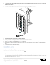
— E. Test Inputs & Alarms Without Breakers
1. Make sure BDFB / BDCBB contains no circuit breakers.
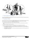
2. Turn on Feed A input power.
• Verify that VDC PWR lamp turns green.
• Verify that FUSE ALM lamp is not lit.
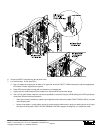
3. Use a DVM with standard .080-in. test probes to verify power and polarity at panel’s VDC test points for Feed A:
• Connect panel RED (-48Vdc) to meter RED (voltage).
• Connect panel BLK (RTN) to meter BLK (common).
4. Use an ohmmeter at alarm monitor to verify alarm conditions.
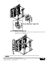
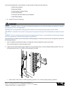
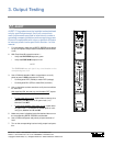
Alarm Board on
Rear of Panel Cover
(1X)
(2X)
Front
Rear
Remove 4 Screws
to Remove Panel Cover


