Telect, Inc. • USA +1.509.926.6000 • Mexico +1.52.33.3836.3700
Poland +1.48.713.239.100 • UK +1.44.1489.889500 • www.telect.com
Copyright © 2002 Telect, Inc., All Rights Reserved • Telect Publication 122645-5 A0
3. Output Testing
ALERT
!
ALERT! This product must be installed and maintained
only by qualified personnel. Verify all connections
meet requirements specified in local electric codes or
operating company guidelines before supplying power.
Protect this equipment with a fuse or breaker sufficient
to interrupt power levels specified in Section 1 of this
manual.
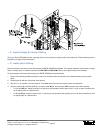
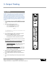
1. For initial startup, make sure all BDFB / BDCBB circuit break-
ers and all inputs at output loads are disabled (disconnected
or off).
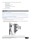
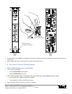
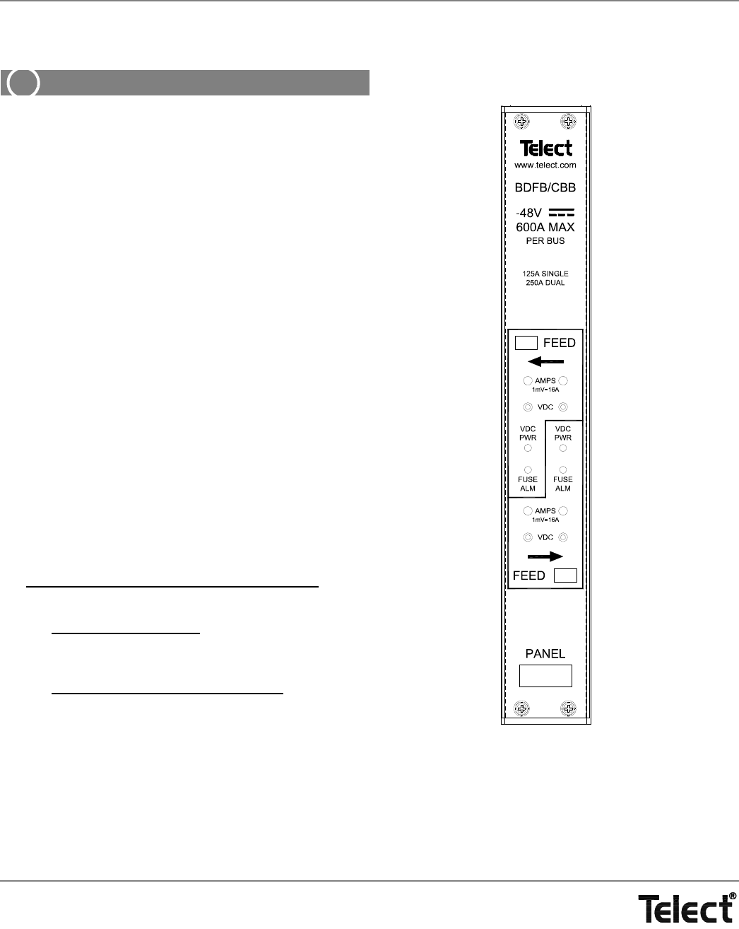
2. With Feed A and B to panel turned on —
• Verify that VDC PWR lamps turn green.
• Verify that FUSE ALM lamps turn red.
NOTE
The FUSE ALM lamp will light if any circuit breaker on the
corresponding bus is off.
3. Use a DVM with standard .080-in. test probes to re-verify
power at panel’s VDC test points for Feed A:
• Connect panel RED (-48Vdc) to meter RED (voltage).
• Connect panel BLK (RTN) to meter BLK (common).
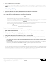
4. Use an ohmmeter at alarm monitor to verify alarm conditions
for each feed.
With input feed OK, but with any circuit breaker OFF
, expect
the following feed conditions:
• For the power alarm circuit
, expect either continuity (0 Ω)
between C and NC poles or an open circuit (∞ Ω)
between C and NO.
• For the circuit breaker (fuse) alarm circuit
, expect either
an open circuit (∞ Ω) between C and NC poles or conti-
nuity (0 Ω) between and C and NO.
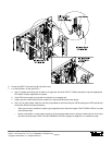
5. Make sure power is disabled at the first load and then turn on
the corresponding BDFB / BDCBB circuit breaker.
6. Use a DVM to test power and polarity at input terminals of
load.
7. Turn on the corresponding load and verify proper load opera-
tion.


