


TNETX3270
ThunderSWITCH 24/3 ETHERNET SWITCH
WITH 24 10-MBIT/S PORTS AND 3 10-/100-MBIT/S PORTS
SPWS043B – NOVEMBER 1997 – REVISED APRIL 1999
18
POST OFFICE BOX 655303 • DALLAS, TEXAS 75265
interface description
DIO interface
The DIO interface is a general-purpose interface that can be used with a wide range of microprocessor or
computer systems. The interface supports external DMA controllers.
This interface can be used to configure the TNETX3270 using an optional attached CPU (or EEPROM), and
to access statistics registers. In addition, this allows access to an internal network management (NM) port that
can be transferred between the CPU and the TNETX3270 to support spanning tree, SNMP, and RMON. Either
the CPU can read and write packets directly under software control or an external DMA controller can be used
to improve performance.
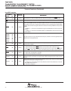
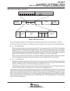
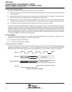
When accessing the statistics values from the DIO port, it is necessary to perform four 1-byte DIO reads to obtain
the full 32-bit counter. Counters always should be read in ascending byte-address order (0, 1, 2, 3). To prevent
the counter being updated while reading the four bytes, the entire 32-bit counter value is transferred to a holding
register when byte 0 is read.
receiving/transmitting management frames
Frames originating within the host are written to the NM port via the NMRxcontrol and NMdata registers. Once
a frame has been fully written, it is then received by the switch and routed to the destination port(s).
Frames that were routed to this port from any of the switch ports are placed in a queue until the host is ready
to read them via the NMTxcontrol and NMdata registers. They then are effectively transmitted out of the switch.
SDMA
can be used to transmit or receive management frames (the SAD1–SAD0 pins are ignored when SDMA
is asserted) (see Table 3). When SDMA is asserted, the switch uses the value in the DMAaddress register
instead of the DIO address registers to access frame data (this also can be used to access the switch statistics).
STXRDY and SRXRDY, the interrupts, freebuffs, eof, sof, and iof mechanisms can be used, as desired, to
prevent unwanted stalls on the DIO bus during busy periods.
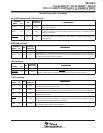
Table 3. DMA Interface Signals
SIGNAL DESCRIPTION
SDMA Automatically sets up DIO address using the DMAaddress register
STXRDY Indicates that at least one data frame buffer can be read by the management CPU
SRXRDY Indicates that the management CPU can write a frame of any size up to 1535 bytes
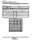
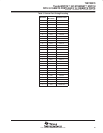
state of DIO signals during hardware reset
The CPU can perform a hardware reset by writing to an address in the range 0x4000–0x5FFF (writes to a DMA
address in this range have no effect on reset). This is equivalent to asserting the hardware RESET
pin. During
hardware reset, the output and bidirectional DIO pins behave as shown in Table 4.
Table 4. DIO Interface During Hardware Reset
DIO INTERFACE
SIGNAL
STATE DURING HARDWARE RESET
SDATA7–SDATA0 High impedance. Resistively pulled up.
SRDY High impedance. Resistively pulled up.
SRXRDY Driven high
STXRDY Driven low