TNETX3270
ThunderSWITCH 24/3 ETHERNET SWITCH
WITH 24 10-MBIT/S PORTS AND 3 10-/100-MBIT/S PORTS
SPWS043B – NOVEMBER 1997 – REVISED APRIL 1999
38
POST OFFICE BOX 655303 • DALLAS, TEXAS 75265
SDRAM-type and quantity indication
Before beginning operation (by writing to the start bit of Syscontrol), it is necessary to indicate to the SDRAM
interface whether × 8 or × 16 SDRAMs are being used. This is done by setting the bit in the RAMsize register
(by 8 = 0 for × 16, by 8 = 1 for × 8) during the load from EEPROM or via a DIO write. It also is necessary to inform
the SDRAM interface of the quantity of external SDRAM available. This is done by writing to the RAMsize
register, while at the same time setting the × 8 or × 16 SDRAMs.
initialization
SDRAMs require controlled initialization. Specifically, SDRAMs require up to 200 µs of inactivity after power has
been supplied, during which they are supplied only with an active CLK. The system designer must ensure that
this inactivity period is observed while TNETX3270 is held in hardware or software reset.
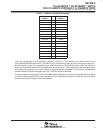
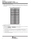
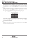
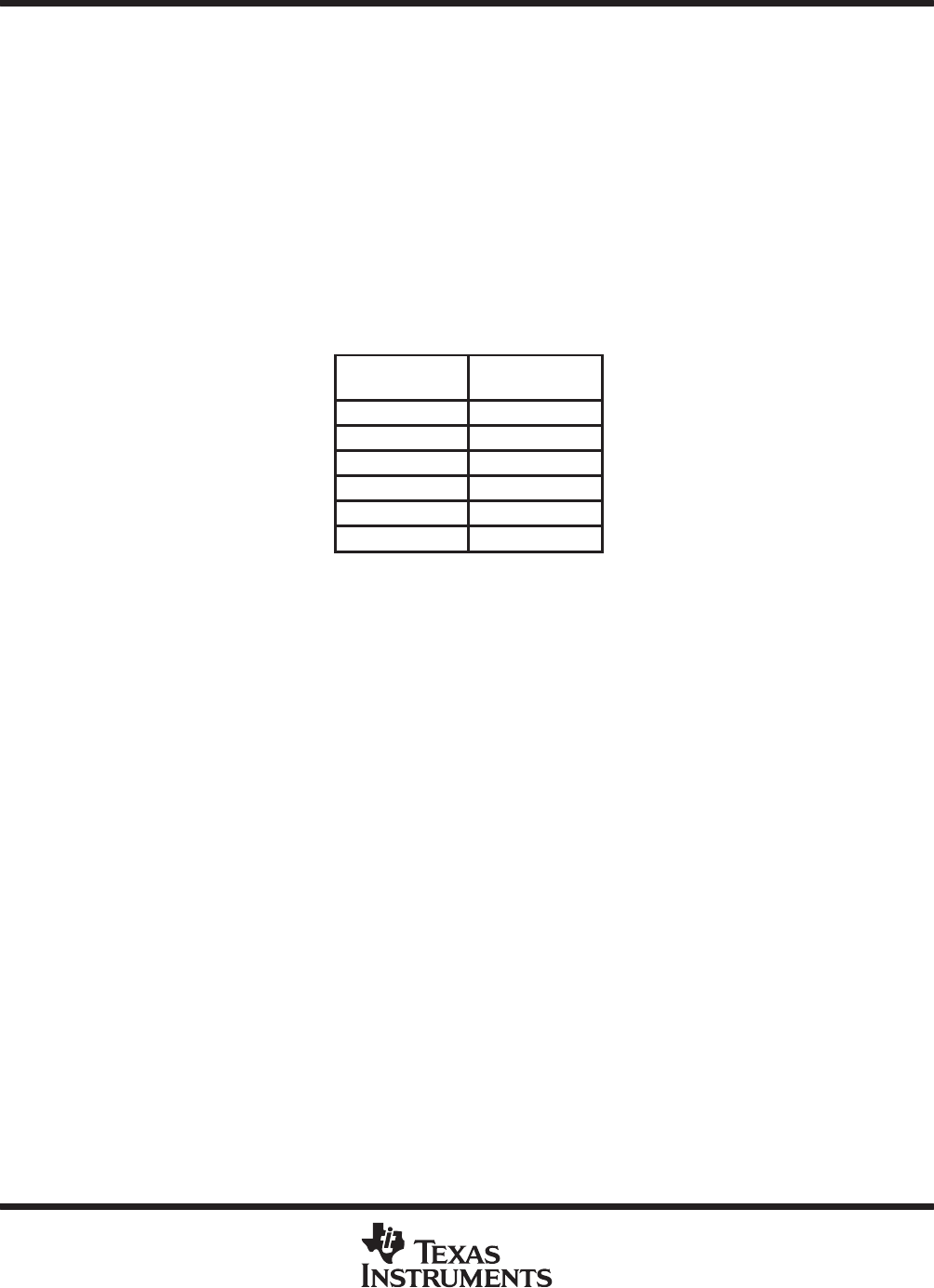
Table 17 shows the state of the SDRAM interface terminals during hardware or software reset.
Table 17. SDRAM Interface Terminal State During Hardware or Software Reset
TNETX3270
TERMINAL
STATE
DURING RESET
DA13–DA00 Driven high
DRAS Driven high
DCAS Driven high
DW Driven high
DCLK Active
DD31–DD00 High impedance
Any other SDRAM requirements during this period that need to be observed, such as the state of chip selects
and clock-enable and data-mask controls, also are the responsibility of the system designer. This SDRAM
interface does not drive the DD bus during hardware or software reset, or following either reset, until the SDRAM
initialization process has been completed.
refresh
After the initialization process, the SDRAM interface then performs 4096 REFR commands at least every 64 ms.
SDRAM data is, however, lost during any subsequent resets, as the SDRAM interface does not issue any REFR
commands during any hardware or software reset.


