


TNETX3270
ThunderSWITCH 24/3 ETHERNET SWITCH
WITH 24 10-MBIT/S PORTS AND 3 10-/100-MBIT/S PORTS
SPWS043B – NOVEMBER 1997 – REVISED APRIL 1999
36
POST OFFICE BOX 655303 • DALLAS, TEXAS 75265
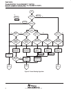
10-/100-Mbit/s port configuration in a managed switch
The 10-/100-Mbit/s ports can be configured in a managed switch using either of the following procedures:
1. The management CPU sets the req10 and reqhd bits of the Portxcontrol registers as required while the
PHYs are held in reset. If either of these bits becomes a 1, the corresponding terminal is not pulled low and
thus, floats high. (The reqnp bit also can be loaded from EEPROM to enable/disable pause-frame control
in the MAC, but this cannot be communicated to the PHY. The system designer should ensure that the MAC
and PHY operate using the same pause-frame regime.)
2. The PHYs are then released from reset and either:
a. Look at the MxxFORCE10
and MxxFORCEHD terminals and configure themselves as specified (if not
autonegotiating), or as the highest common denominator with the link partner, if they are
autonegotiating.
b. Ignore TNETX3270 requests and configure themselves in some other manner.
3. The PHYs (or external system) subsequently drive MxxFORCE10
and MxxFORCEHD low for those
features that are supported only at the lower performance. These are continuously sampled into the
Portxstatus register.
4. The MACs then operate as indicated by the Portxstatus register.
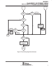
5. The operating state of the PHYs subsequently can be altered by using the IEEE Std 802.3u MII
management interface. Any change of state should be reflected on the values presented on MxxFORCE10
and MxxFORCEHD so that the MACs are similarly reconfigured.
Or:
1. MxxFORCE10
and MxxFORCEHD should not be connected to anything.
2. Software uses the IEEE Std 802.3u MII management interface to configure the PHYs to the required
operating conditions, possibly interrogating the PHY as to the results of autonegotiation.
3. The MACs should then be set to operate in the required manner by writing the appropriate values to the
req10 and reqhd bits in the Portxcontrol register. This causes MxxFORCE10
and MxxFORCEHD to reflect
the operating conditions that are sampled into the Portxstatus registers to configure the MACs. The reqnp
bit also should be set to 1 for those PHYs that are configured to support IEEE Std 802.3x pause frames.
This also is communicated to the MACs.
SDRAM interface
All valid frames pass over this interface to the external SDRAM, where they are temporarily buffered between
reception and transmission.
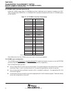
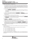
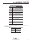
The data bus within the SDRAM interface is 32 bits wide and supports the following configurations:
Two 1M × 16-bit SDRAMs (4 Mbytes of storage)
Four 2M × 8-bit SDRAMs (8 Mbytes of storage)
Two 4M × 16-bit SDRAMs (16 Mbytes of storage)
Four 8M × 8-bit SDRAMs (32 Mbytes of storage)
The interface is clocked at 83.33 MHz, so 12-ns SDRAMS are required. If one of the above configurations is
used, then no additional glue logic is required. The SDRAMs should be connected to the SDRAM interface pins
(see Table 15).