TNETX3270
ThunderSWITCH 24/3 ETHERNET SWITCH
WITH 24 10-MBIT/S PORTS AND 3 10-/100-MBIT/S PORTS
SPWS043B – NOVEMBER 1997 – REVISED APRIL 1999
45
POST OFFICE BOX 655303 • DALLAS, TEXAS 75265
port trunking/load sharing
Port trunking is a technique that allows two or more ports to be parallel connected between switches and
counted as one port to increase the bandwidth between those devices. The trunking algorithm determines on
which of these ports a frame is transmitted, spreading the load evenly across these ports and maintaining packet
order.
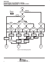
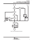
The TNETX3270 supports trunking on the 10-/100-Mbit/s ports. Trunk-port determination is the final step in the
IALE frame-routing algorithm. Once the destination port(s) for a frame has been determined, the port-routing
code is examined to see if any of the destination ports are members of the trunk. If so, the trunking algorithm
is applied to select which port within that trunk transmits the frame – it may or may not be the one currently in
the port-routing code. To determine the destination port within a trunk, bits 3–1 of the source and destination
address are XORed to produce a map index. This map index is used to index to a group of eight internal registers
to determine the destination port. The actual transmit port of a unicast packet is dynamic, based on the eight
internal registers.
Load sharing is similar to trunking, with the following differences:
If the destination address was found in the IALE records when it was looked up, the port-routing code is not
adjusted by the load-sharing/-trunking algorithm.
The 3-bit map index is determined only from the source address as follows:
– Bits 47–32 are XORed to produce the most significant bit of the map index.
– Bits 31–16 are XORed to produce the middle of the map index.
– Bits 15–0 are XORed to produce the least significant bit of the map index.
Once assigned, the tx port for a unicast packet is static.
flow control
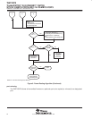
The switch incorporates two forms of flow control: collision based, and IEEE Std 802.3 pause frames.
In either case, the switch recognizes when it is becoming congested by monitoring the size of the free-buffer
queue. When the number of free buffers drops below the specified threshold, the switch prevents frames from
entering the device by issuing the flow control appropriate to each port’s current mode of operation. This
prevents reception of any more frames on those ports until the frame backlog is reduced and the number of free
buffers has risen above the threshold, at which point flow control ceases and frames again can be received.
The default free-buffer threshold after a hardware reset is chosen to ensure that all ports simultaneously can
start reception of a maximum-length frame and ensure complete reception.
The purpose of flow control is to reduce the risk of data loss if a long burst of activity caused the switch to backlog
frames to the point where the memory system is full. However, there is no way to prevent frame reception on
those ports operating in full-duplex mode that have not negotiated IEEE Std 802.3 flow control. Such ports can
exhaust the free buffer queue, with subsequent data loss.
Each 10-/100-Mbit/s port can request collision or IEEE Std 802.3X flow control through internal registers.
Flow control is globally enabled/disabled. Each individual port can request half- or full-duplex or IEEE Std 802.3
flow to be negotiated by the PHY device.
In full duplex, a port does not start transmitting a new frame if the collision pin is active, although the value of
this pin is ignored at other times.


