


TNETX3270
ThunderSWITCH 24/3 ETHERNET SWITCH
WITH 24 10-MBIT/S PORTS AND 3 10-/100-MBIT/S PORTS
SPWS043B – NOVEMBER 1997 – REVISED APRIL 1999
30
POST OFFICE BOX 655303 • DALLAS, TEXAS 75265
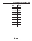
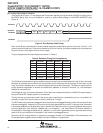
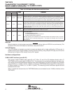
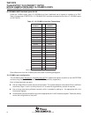
Table 10. LED Status Bit Definitions and Shift Order
ORDER
NAME
FUNCTION
slast = 0 slast = 1
NAME
FUNCTION
1–7 1–7 0 Zero. Dummy data for first seven of 48 LEDCLK cycles.
8–19 35–46 SW0–SW11
Software LEDs 0–11. These allow additional software-controlled status to be displayed. These
12 LEDs reflect the values of bits 0–11 of the swled field in LEDControl
at the moment that the LED
interface samples them. If this occurs between writes to the most significant and least significant
bytes of LEDControl, these values appear on the LEDs, separated by 1/16th of a second.
20–46 8–34 P00–P26
Port status LEDs 00–26. These 27 LEDs indicate the status of ports 00–26, in this order (port 00
is output first). Note that port 27 (management port) does not have an LED. The transmit multicast
content of these bits can be controlled by the txais bit in LEDControl. Note that IEEE Std 802.3X
pause frames never appear on the LEDs as port activity. The port’s LED toggles each 1/16th of a
second if there was any frame traffic (other than pause frames) on the port during the previous
1/16th of a second.
47 47 FLOW
Flow control. LED is on when the internal flow control is enabled and active. Active means that flow
control is asserted during the previous 1/16th of a second.
48 48 FAULT
Fault. LED indicates:
– the EEPROM CRC is invalid.
– an external DRAM parity error has occurred.
– the fitled in LEDControl has been set.
The CRC and parity error indications are cleared by hardware reset (terminal or DIO). The CRC
error indication also is cleared by setting load to 1. The parity error indication also is cleared by
setting start to 1.
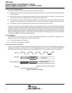
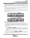
lamp test
When the device is in the hardware reset state, LEDDATA is driven high and LEDCLK runs continuously. This
causes all LEDs to be illuminated and serves as a lamp test function.
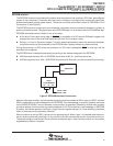
multi-LED display
The LED interface is intended to provide the lowest-cost display with a single multifunction LED per port. In
systems requiring a full-feature display (more than levels of activity) using multiple LEDs per port, this can be
achieved by driving the LEDs directly from the PHY signals.
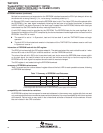
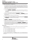
hardware configurations
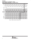
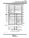
10-Mbit/s MAC interfaces (ports 00–23)
Each group of eight 10-Mbit/s ports (ports 00 to 07, 08 to 15, and 16 to 23) interfaces directly with a TI
TNETE2008, which contains eight 10-Mbit/s PHYs. This interface is time multiplexed between the eight ports,
with receive and transmit data being transferred over nibble-wide buses. Any given port needs only to transfer
data at 2.5 MHz (i.e., 2.5 MHz × 4 bits = 10 Mbit/s), but because TNETE2008 contains eight PHYs, the frequency
of nibble transfers is 20 MHz (i.e., 2.5 MHz × 8 ports). The remaining control and status signals also are
transferred at this rate.
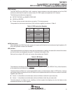
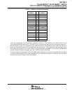
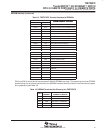
Table 11 shows how the terminals of a TNETE2008 device are connected to each 10-Mbit/s interface on the
TNETX3270.