


AR-B1375/AR-B1376 User s Guide
3-2
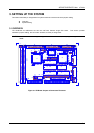
3.2 SYSTEM SETTING
Jumper pins allow you to set specific system parameters. Set them by changing the pin location of jumper blocks.
(A jumper block is a small plastic-encased conductor [shorting plug] that slips over the pins.) To change a jumper
setting, remove the jumper from its current location with your fingers or small needle-nosed pliers. Place the
jumper over the two pins designated for the desired setting. Press the jumper evenly onto the pins. Be careful not
to bend the pins.
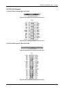
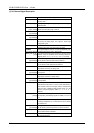
We will show the locations of the AR-B1375 and AR-B1376 jumper pins, and the factory-default setting.
CAUTION: Do not touch any electronic component unless you are safely grounded. Wear a grounded wrist strap
or touch an exposed metal part of the system unit chassis. The static discharges from your fingers can
permanently damage electronic components.
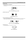
3.2.1 Keyboard Connector
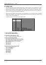
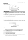
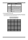
(1) 6-Pin Mini DIN Keyboard Connector (CN3)
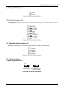
CN3 is a Mini-DIN 6-pin connector. This keyboard connector is PS/2 type keyboard connector. This connector is
also for a standard IBM-compatible keyboard with the keyboard adapter cable.
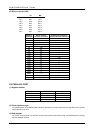
1 DATA
3 GND
2 N.C.
6 N.C.
4 VCC
1
2
3
4
5
6
5 CLOCK
CN3
Front View
Figure 3-2 CN3: 6-Pin Mini Din Keyboard Connector
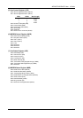
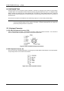
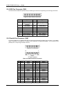
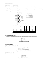
(2) AUX. Keyboard Connector (J4)
We can use a PC/AT compatible keyboard to connecting the provided adapter cable between J4 and the keyboard.
The pin assignments of J4 connector are as follows:
2 DATA
4 GND
1 CLOCK
5 VCC
3 N.C.
J4
Figure 3-3 J4: AUX. Keyboard Connector