AR-B1375/AR-B1376 User s Guide
2-1
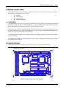
2. SYSTEM CONTROLLER
This chapter describes the major structure of the AR-B1375 and AR-B1376 CPU board. The following topics are
covered:
z Microprocessor
z DMA Controller
z Keyboard Controller
z Interrupt Controller
z Real-Time Clock and Non-Volatile RAM
z Timer
z Serial Port
z Parallel Port
2.1 MICROPROCESSOR
The AR-B1375 and AR-B1376 use the ALI M6117 CPU, it is designed to perform like Intel’s 386SX system with
deep green features.
The 386SX core is the same as M1386SX of Acer Labs. Inc. and 100% object code compatible with the Intel
386SX microprocessor. System manufacturers can provide 386 CPU based systems optimized for both cost and
size. Instruction pipelining and high bus bandwidth ensure short average instruction execution times and high
system throughput. Furthermore, it can keep the state internally from charge leakage while external clock to the
core is stopped without storing the data in registers. The power consumption here is almost zero when clock stops.
The internal structure of this core is 32-bit data and address bus with very low supply current. Real mode as well
as Protected mode are available and can run MS-DOS, MS-Windows, OS/2 and UNIX.
2.2 DMA CONTROLLER
The equivalent of two 8237A DMA controllers are implemented in the AR-B1375/AR-B1376 board. Each controller
is a four-channel DMA device that will generate the memory addresses and control signals necessary to transfer
information directly between a peripheral device and memory. This allows high speeding information transfer with less
CPU intervention. The two DMA controllers are internally cascaded to provide four DMA channels for transfers to
8-bit peripherals (DMA1) and three channels for transfers to 16-bit peripherals (DMA2). DMA2 channel 0 provides
the cascade interconnection between the two DMA devices, thereby maintaining IBM PC/AT compatibility.
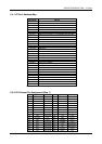
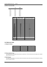
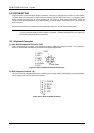
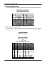
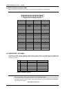
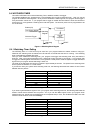
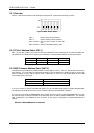
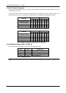
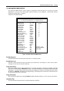
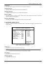
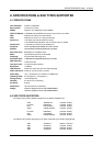
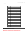
Following is the system information of DMA channels:
DMA Controller 1 DMA Controller 2
Channel 0: Spare Channel 4: Cascade for controller 1
Channel 1: IBM SDLC Channel 5: Spare
Channel 2: Diskette adapter Channel 6: Spare
Channel 3: Spare Channel 7: Spare
Table 2-1 DMA Channel Controller