AR-B1375/AR-B1376 User s Guide
3-8
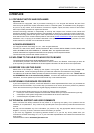
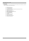
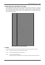
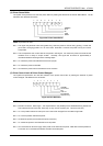
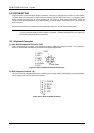
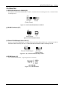
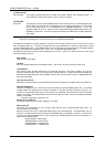
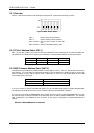
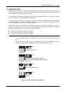
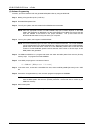
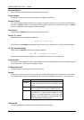
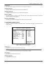
(5) RS-232 Connector (CN7 & DB2)
There are two serial ports with EIA RS-232 interface on the AR-B1375 or AR-B1376. COM A uses one on-board
D-type 9-pin male connector (DB2) which is located at the right side of the card, and COM B uses one 10-pin
header (CN7) which is located at the upper of the card. To configure these two serial ports, use the BIOS Setup
program to do well, and adjust the jumpers on J6 and J7.
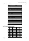
The pin assignments of the DB2 and CN7 for serial port A & B are as follows:
DB2 (COM A)
CN7 (COM B)
6-DSR
7-RTS
8-CTS
9-RI
1-DCD
2 RXD
3 TXD
4-DTR
5 GND
1
2
Figure 3-15 CN7 & DB2: RS-232 Connector
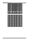
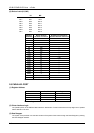
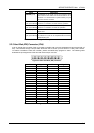
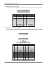
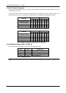
CN7 DB2 Signal CN7 DB2 Signal
1 1 -DCD 2 6 -DSR
3 2 RXD 4 7 -RTS
5 3 TXD 6 8 -CTS
7 4 -DTR 8 9 -RI
9 5 GND 10 -- Not Used
Table 3-2 Serial Port Pin Assignment
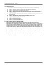
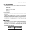
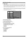
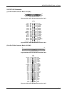
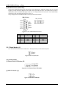
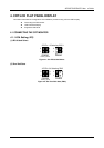
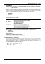
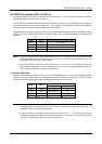
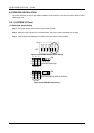
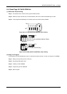
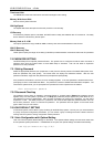
3.2.7 Reset Header (J1)
J1 is used to connect to an external reset switch. Shorting these two pins will reset the system.
1 Reset+
2 Reset-
Figure 3-16 J1: Reset Header
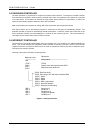
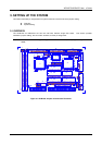
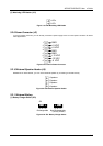
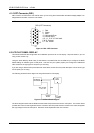
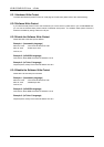
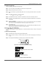
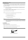
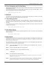
3.2.8 LED Header
(1) External Power LED Header (J2)
123
1 Power LED+
2 No Connect
3 Power LED-
Figure 3-17 J2: External Power LED Header
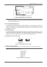
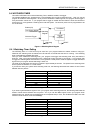
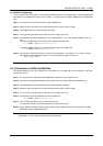
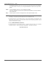
(2) HDD LED Header (J8)
1
2
LED+
LED-
Figure 3-18 J8: HDD LED Header