


AR-B1375/AR-B1376 User s Guide
3-6
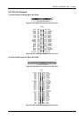
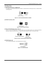
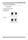
3.2.4 FDD Port Connector (CN5)
The AR-B1375 and AR-B1376 provide a 34-pin header type connector for supporting up to two floppy disk drives.
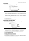
1
2
Figure 3-9 CN5: FDD Port Connector
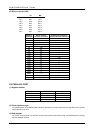
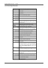
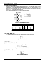
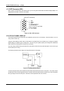
Pin Signal Pin Signal
1-33(odd) GROUND 18 DIRECTION
2 -REDUCED WRITE
CURRENT
20 -STEP OUTPUT PULSE
4 NOT USED 22 -WRITE DATA
6 NOT USED 24 -WRITE ENABLE
8 -INDEX 26 -TRACK 0
10 -MOTOR ENABLE A 28 -WRITE PROTECT
12 -DRIVE SELECT B 30 -READ DATA
14 -DRIVE SELECT A 32 -SIDE 1 SELECT
16 -MOTOR ENABLE B 34 DISK CHANGE
Table 3-1 FDD Pin Assignment
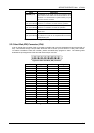
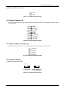
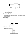
3.2.5 Parallel Port Connector (CN6)
To use the parallel port, an adapter cable has connected to the CN6 (26-pin header type) connector. This adapter
cable is mounted on a bracket and is included in your AR-B1375 or AR-B1376 package. The connector for the
parallel port is a 25 pin D-type female connector.
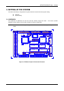
1
2
1
14
13
25
DB-25
D-Type Connector
Parallel Port Connector
Figure 3-10 CN6: Parallel Port Connector
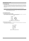
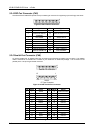
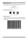
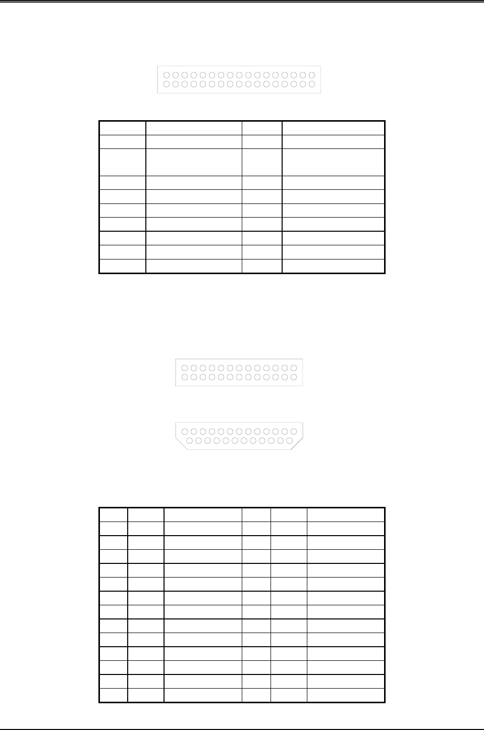
CN6 DB-25 Signal CN6 DB-25 Signal
1 1 -Strobe 2 14 -Auto Form Feed
3 2 Data 0 4 15 -Error
5 3 Data 1 6 16 -Initialize
7 4 Data 2 8 17 -Printer Select In
9 5 Data 3 10 18 Ground
11 6 Data 4 12 19 Ground
13 7 Data 5 14 20 Ground
15 8 Data 6 16 21 Ground
17 9 Data 7 18 22 Ground
19 10 -Acknowledge 20 23 Ground
21 11 Busy 22 24 Ground
23 12 Paper 24 25 Ground
25 13 Printer Select 26 -- No Connect
Table 3-1 Parallel Port Pin Assignment