


AR-B1375/AR-B1376 User s Guide
3-5
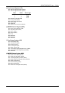
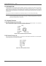
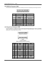
Name Description
-MASTER [Input] The MASTER is the signal from the I/O processor which
gains control as the master and should be held low for a
maximum of 15 microseconds or system memory may be
lost due to the lack of refresh
-MEMCS16
[Input, Open collector]
The Memory Chip Select 16 indicates that the present data
transfer is a 1-wait state, 16-bit data memory operation
-IOCS16
[Input, Open collector]
The I/O Chip Select 16 indicates that the present data
transfer is a 1-wait state, 16-bit data I/O operation
OSC [Output] The Oscillator is a 14.31818 MHz signal used for the color
graphic card
-ZWS
[Input, Open collector]
The Zero Wait State indicates to the microprocessor that
the present bus cycle can be completed without inserting
additional wait cycle
Table 3-9 I/O Channel Signal’s Description
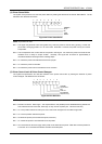
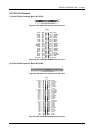
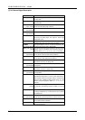
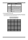
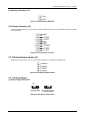
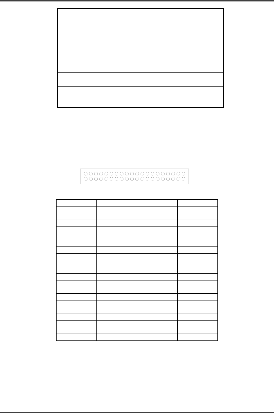
3.2.3 Hard Disk (IDE) Connector (CN4)
A 40-pin header type connector (CN4) is provided to interface with up to two embedded hard disk drives (IDE AT
bus). This interface, through a 40-pin cable, allows the user to connect up to two drives in a “daisy chain” fashion.
To enable or disable the hard disk controller, please use BIOS Setup program to select. The following table
illustrates the pin assignments of the hard disk drive’s 40-pin connector.
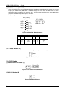
1
2
Figure 3-8 CN4: Hard Disk (IDE) Connector
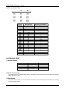
Pin Signal Pin Signal
1 -RESET 2 GROUND
3 DATA 7 4 DATA 8
5 DATA 6 6 DATA 9
7 DATA 5 8 DATA 10
9 DATA 4 10 DATA 11
11 DATA 3 12 DATA 12
13 DATA 2 14 DATA 13
15 DATA 1 16 DATA 14
17 DATA 0 18 DATA 15
19 GROUND 20 NOT USED
21 NOT USED 22 GROUND
23 -IOW 24 GROUND
25 -IOR 26 GROUND
27 -IORDY 28 BALE
29 NOT USED 30 GROUND
31 IRQ 14 32 -IOCS16
33 SA 1 34 NOT USED
35 SA 0 36 SA 2
37 -CS 0 38 -CS 1
39 HD LED 40 GROUND
Table 3-1 HDD Pin Assignment