


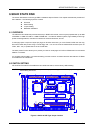


AR-B1375/AR-B1376 User s Guide
6-9
6.4.3 Small Page 5V FLASH ROM Disk
(1) Switch and Jumper Setting
Step 1:
Use jumper block to set the memory type as ROM (FLASH).
Step 2:
Select the proper I/O base port, firmware address, disk drive number and EPROM type on SW1.
Step 3:
Insert programmed EPROM(s) or FLASH(s) chips into sockets starting at MEM1.
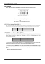
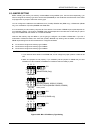
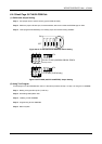
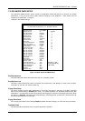
ON
123456
OFF
Figure 6-8 5V FLASH (29CXXX & 28EEXXX) Switch Setting
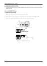
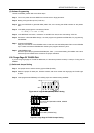
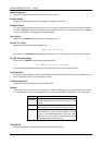
5V/12V FLASH (64KX8M 128KX8, 256KX
8
Factory Preset
2
1
3
ABC
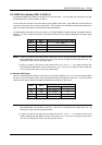
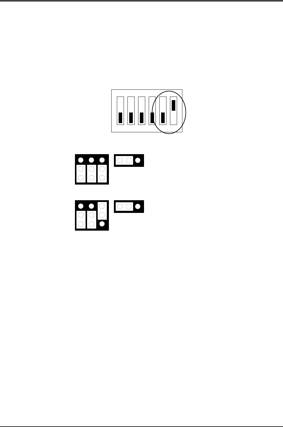
5V FLASH (512KX8 only)
2
1
3
ABC
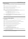
123
JP4
M1~M3
123
JP4
M1~M3
Figure 6-9 5V FLASH (29CXXX & 28EEXXX) Jumper Setting
(2) Using Tool Program
If small page 5V FLASH EPROMs are used, it is the same procedure as step 1 to step 4 of using the UV EPROM:
Step 1:
Making a Program Group File (*.PGF file)
Step 2:
Generating ROM pattern files
Step 3:
Installing FLASH EPROMs
Step 4:
Programming FLASH EPROMs
Step 5:
Reboot system