


AR-B1375/AR-B1376 User s Guide
6-1
6.SOLID STATE DISK
The section describes the various type SSDs’ installation steps as follows. This chapter describes the procedure of
the installation. The following topics are covered:
z Overview
z Switch Setting
z Jumper Setting
z ROM Disk Installation
6.1 OVERVIEW
The AR-B1375 and AR-B1376 provides three 32-pin JEDEC DIP sockets, which may be populated with up to 3MB
of EPROM or 1.5MB of FLASH or 1.5MB of SRAM disk. It is ideal for diskless systems, high reliability and/or high
speed access applications, controller for industrial or line test instruments, and etc.
If small page (less or equal 512 bytes per page) 5V FLASHs were used, you could format FLASH disk and copy
files onto FLASH disk just like using a normal floppy disk. You can use all of the related DOS command (such as
COPY, DEL…etc.) to update files on the 5V FLASH disk.
The write protect function allows you to prevent your data on small page 5V FLASH or SRAM disk from accidental
deletion or overwrite.
An on-board Lithium battery or an external battery pack that could be connected ensures data retention of SRAM
to the AR-B1375 and AR-B1376.
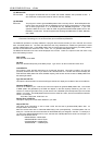
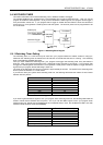
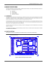
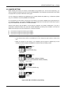
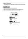
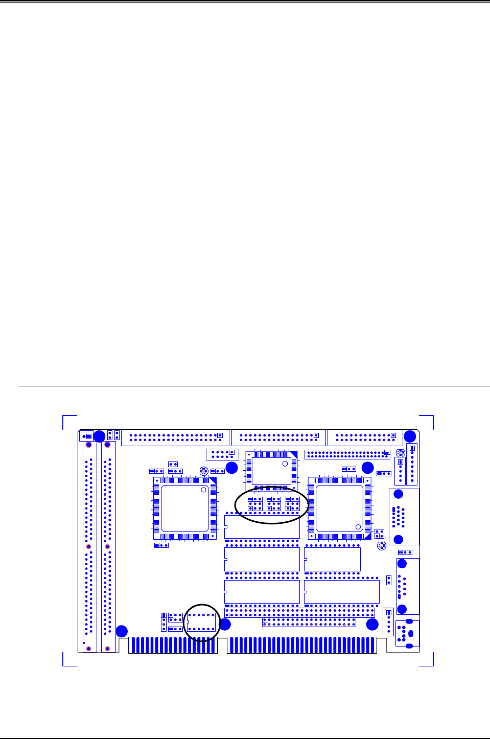
6.2 SWITCH SETTING
We will show the locations of the AR-B1375 and AR-B1376 switch, and the factory-default setting.
CAUTION: The switch setting needs to adjust with the jumpers setting, make sure the jumper settings and the
switch setting are correct.
M1
M2
M3
MEM1
MEM2
MEM3
ABC ABC ABC
1
2
3
11
22
33
11
1
1
2
1
1
1
2
1
1
1
1
2
1
CN1
H11H10
H9
SW1
1
1
0
4
1
0
5
U3
P5
P3
P1
CN8
CN4
JP1
JP5
1
1
0
4
105
U34
U10
1
3
1
5
1
8
1
1
0
0
5
0
U12
CN5
U11
U33
U32
U31
CN6
CN7
J3
J4
CN9
J5
P6
P4
P2
JP6
JP4
JP3
JP2
J9
J7
J6
J2
J11
JP7
J10
J8J1
LED3
LED2
LED1
1
S
I
M
M
2
DB2
DB1
H5
H8
CN2
H7
H4
H6
CN3
1
S
I
M
M
1
BUS2
BUS1
C
N
1
Figure 6-1 Switch & SSD Type Jumper Location