Error! Style not defined. Error! Style not defined. 4 Replacement Procedures
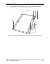
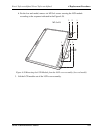
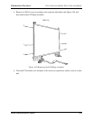
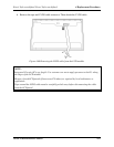
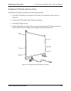
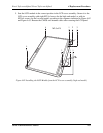
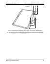
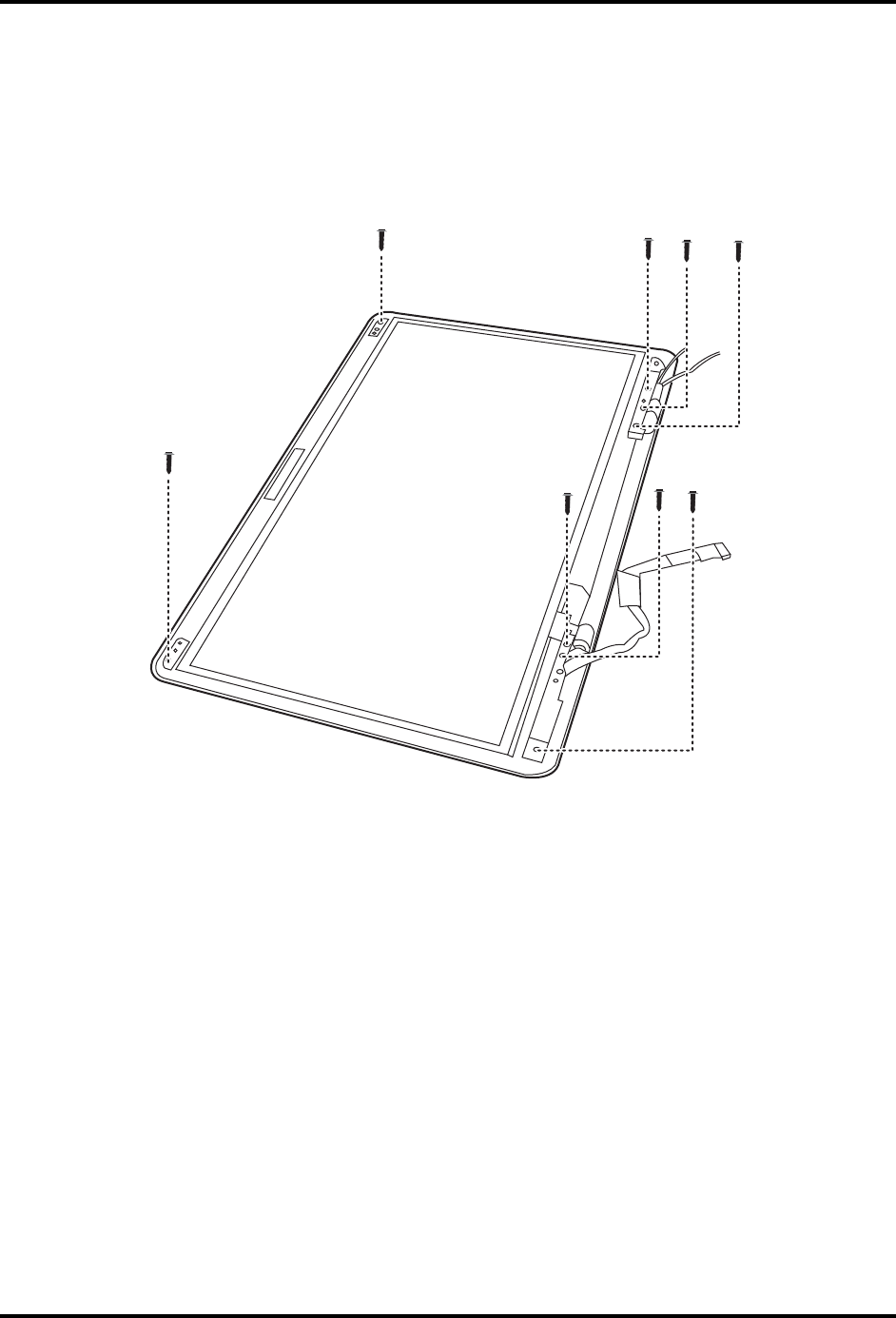
5. Seat the LCD module in the correct position in the LCD cover assembly. Secure it to the
LCD cover assembly with eight M2.5x4 screws for the high-end model, or with six
M2.5x4 screws for the low-end model, according to the sequence indicated in Figure 4.62
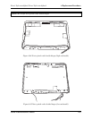
and Figure 4.63. Reroute the CMOS and Antenna cables after securing the LCD panel.
4
1 2 3
M2.5x4*8
4
1
2
3
Figure 4.62 Installing the LCD Module from the LCD cover assembly (high-end model)
Satellite A500D Maintenance Manual 4-63


