


4 Replacement Procedures 4.9 Cover assembly
Installing the cover assembly
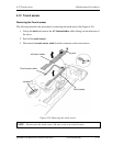
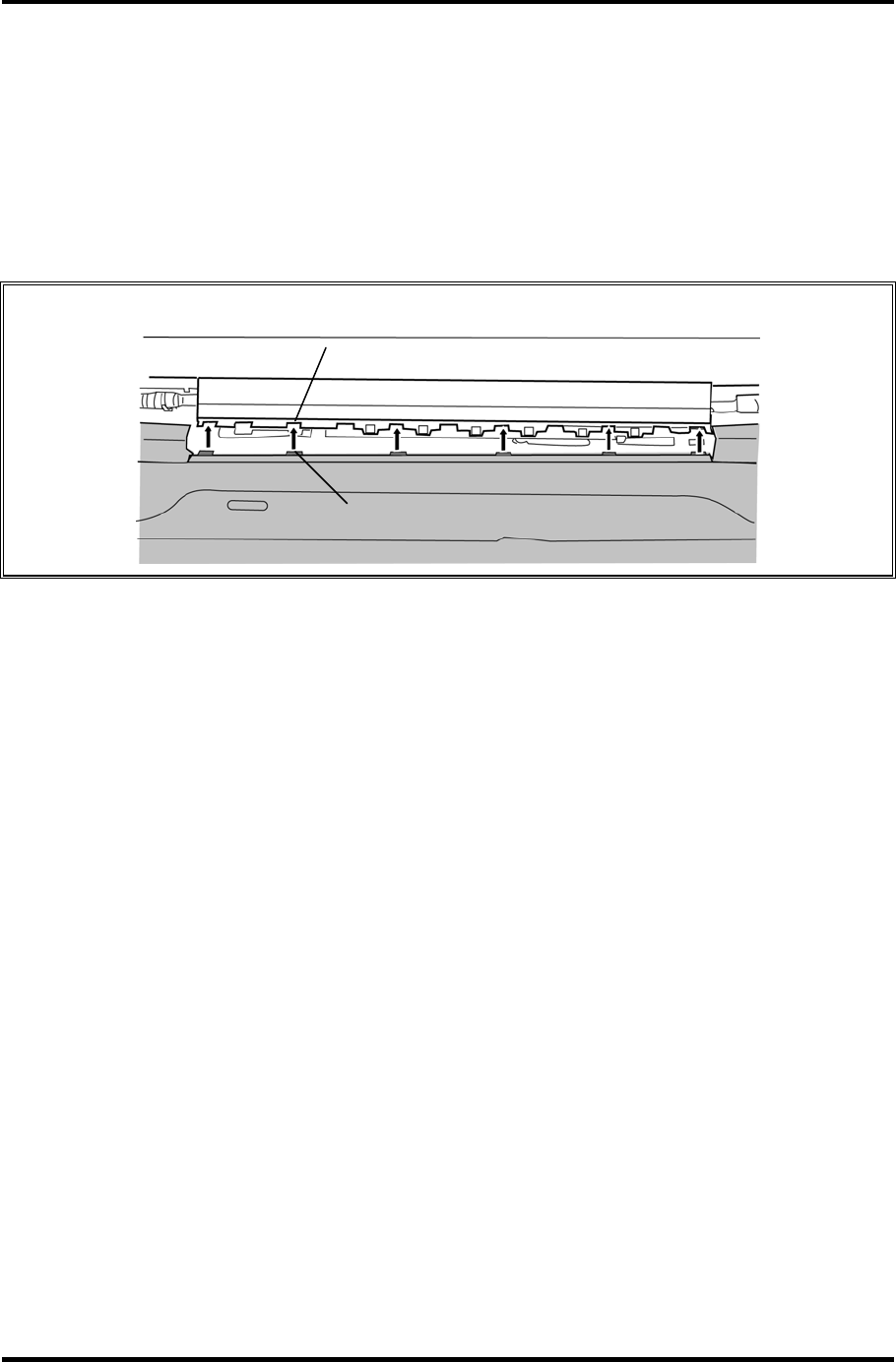
The following describes the procedure for installing the cover assembly (See Figure 4-17 to
4-21).
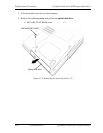
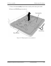
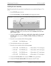
1. Set the WL SW cover to the slot.
2. Set the cover assembly to the base assembly while engaging the latches.
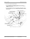
CAUTION: Set the latches of the cover assembly under the guide of the LCD unit.
Guide
Latch
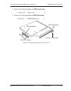
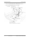
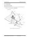
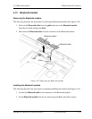
3. Connect the camera/microphone cable and Bluetooth cable to the connector
CN9550 and CN4400 on the system board and stick the insulator (HNS HLD KB
INSULATOR) in place.
4. Connect the touch sensor cable, power switch cable, volume cable and touch pad
SW/LED cable to the connector CN9650, CN3300, CN3330 and CN3240 on the
system board.
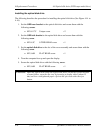
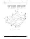
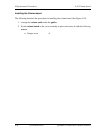
5. Secure the cover assembly with the following screws.
• M2.5×6B FLAT HEAD screw ×6
6. Close the display and turn over the computer.
7. Secure the cover assembly with the following screws.
• M2.5×2.8B FLAT HEAD screw ×2 (Described as “2.8” in the figure)
• M2.5×6B FLAT HEAD screw ×7 (Described as “6B” in the figure)
• M2.5×6C FLAT HEAD screw ×2 (Described as “6C” in the figure)
• M2.5×16B FLAT HEAD screw ×6 (Described as “16” in the figure)
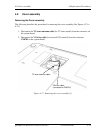
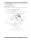
8. Connect the VGA fan cable to the connector CN8781 on the system board.
9. Connect the TV tuner antenna cable to the connector on the TV tuner.
4-34 [CONFIDENTIAL] QOSMIO G50 Maintenance Manual (960-683)