


4.25 VGA fin/VGA/SPURS fin/SPURS 4 Replacement Procedures
QOSMIO G50 Maintenance Manual (960-683) [CONFIDENTIAL] 4-75
Installing the VGA fin/VGA/SPURS fin/SPURS
The following describes the procedure for installing the VGA fin/VGA/SPURS fin/SPURS
(See Figure 4-44 to 4-46).
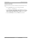
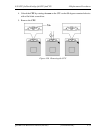
1. If there is already cool sheet on the VGA and SPURS, peel off the cool sheet.
Stick a new cool sheet in place.
NOTE: Do not reuse the cool sheet. Be sure to use a new cool sheet.
Procedures 2 to 3 are for external VGA (NB9E) model.
Procedures 4 to 6 are for external VGA (GM45 or NB9M/9P) and SPURS model.
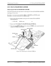
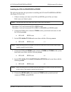
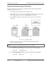
2. Connect the VGA to the connector CN5900 on the system board and secure it with
the following screws.
• M2.0×4B BIND screw ×2
3. Set the VGA holder/VGA fin and secure them with the following screws.
• M2.0×4B BIND screw ×3
NOTE: When securing the VGA holder, be sure to secure the screws in the order of the
number marked on the holder.
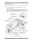
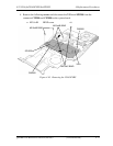
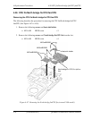
4. Connect the VGA and SPURS to the connector CN5900 and CN2800 on the system
board and secure them with the following screws.
• M2.0×4B BIND screw ×6
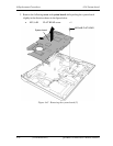
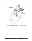
5. Set the VGA holder/VGA fin/SPURS holder/SPURS fin and secure them with the
following screws.
• M2.0×4B BIND screw ×6
NOTE: When securing the VGA holder and SPURS holder, be sure to secure the screws
in the order of the number marked on the holder.
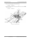
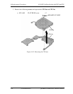
6. Connect the SPURS cable to the connector CN2801 on the system board and
connector CN7901 on the SPURS.