


4.14 Touch pad/Fingerprint sensor board/LED board 4 Replacement Procedures
Installing the touch pad/Fingerprint sensor board/LED board
The following describes the procedure for installing the touch pad/fingerprint sensor
board/LED board (See Figure 4-26 to 4-30).
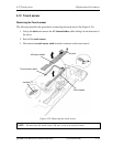
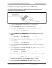
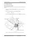
NOTE: When using a new touch pad, stick the insulator (T-PAD BACK INSULATOR)
on the touch pad.
Insulator (T-PAD BACK INSULATOR)
Touch pad
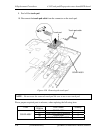
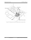
1. Connect the touch pad cable to the connector on a new touch pad.
2. Stick the touch pad to the slot of the cover assembly in place.
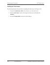
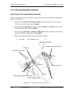
3. Set the plate to the LED board and secure them with the following screw.
• M2.5×2.8B FLAT HEAD screw ×1
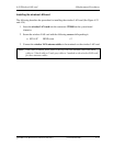
4. Set the LED board to the touch pad plate and secure them with the following
screws.
• M2.5×2.8B FLAT HEAD screw ×2
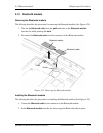
5. Set the Fingerprint sensor board to the LED board and secure them with the
following screw.
• M2.5×2.8B FLAT HEAD screw ×1
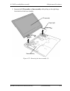
6. Connect the Fingerprint sensor board cable to the connector on the Fingerprint
sensor board.
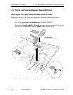
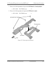
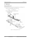
7. Set the Fingerprint sensor board/LED board to the guides of the cover assembly
and secure it with following screws.
• M2.0×4B BIND screw ×2
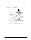
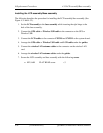
8. Connect the touch pad cable to the connector on the Fingerprint sensor board/LED
board.
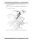
9. Connect the touch pad SW/LED cable to the connector on the LED board and
arrange the LED board cable under the guides of the cover assembly.
10. Stick the
glass tape and aluminum tape (AL TAPE LED FFC) in place.
QOSMIO G50 Maintenance Manual (960-683) [CONFIDENTIAL] 4-47