


16
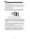
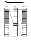
data will be the data obtained from registers 0xFE03, 0xFE04, 0xFE06, and 0xFD00
(in that order).
Note that the settings of the programmable address registers (0x6000 ∼ 0x601F) are
stored in the MDB-100’s nonvolatile EEPROM. Therefore, do not write to any of
these registers more than 100,000 times. Typically, these registers would only be
written to once, when the interface and Modbus network are first commissioned.
When the programmable pointer registers are modified, the changes are made
effective in the MDB-100 immediately (the MDB-100 does not need to be reset for the
changed values to take effect).
9.3 Loss of Communications Timer Function
A configurable "loss of communications" (network watchdog) timer function is
provided, which can detect communication losses and perform certain actions if a
valid packet is not received and processed within a set time period.
MDB-100 register 0x6100 sets the loss of communication time value (adjustable from
100ms to 60.000s in 1ms increments, factory setting = 10.000s). If a valid
(exception-free) reception-response or exception-free broadcast does not take place
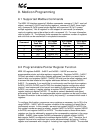
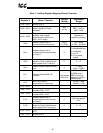
within this time limit, the timer will expire. If the timer expires, 5 possible actions can
occur for each connected drive, as set by the value of registers 0x6101 and 0xE101
(loss of communications action for drive A and drive B, respectively):
Register
0x6101 / 0xE101
Setting
Action Taken Upon Timeout
0 (default) No action: ignore timeout
1 Decelerated stop
2 Coast stop
3 Trip “E” (emergency off)
4 Run a preset speed
When a network timeout is detected, the timeout action is performed. When
communications are once again reestablished, the timer function is automatically
reset and will once again begin to monitor network receptions. However, any actions
performed as a result of the timeout occurring will not be reversed by the MDB-100
once communications are reestablished; the Modbus master’s application must
explicitly modify the affected conditions to fully return the drive to its previous state.
Setting 0 is the default setting; when a communications timeout occurs, no action will
be taken.
For setting 1 (decelerated stop), the drive will stop in a controlled manner if it was
running. This action clears bit #10 in the selected drive’s communication command
bit structure (register 0x7A00 / 0xFA00 - also the same data as write-only coil #10 /
#26). Note that the “communication command valid” bit of register 0x7A00 / 0xFA00
(bit #15 of each register, or write-only coil #15 / #31) must already be set by the
master application for this timeout action to control the drive.