17
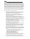
For setting 2 (coast stop), the drive will coast stop (free run) if it was running. This
action clears bit #10 in the selected drive’s communication command bit structure
(register 0x7A00 / 0xFA00 - also the same data as write-only coil #10 / #26) and sets
bit #11 (same as coil #11 / #27). Note that the “communication command valid” bit of
register 0x7A00 / 0xFA00 (bit #15 of each register, or write-only coil #15 / #31) must
already be set by the master application for this timeout action to control the drive.
For setting 3 (trip “emergency off”), the drive will trip “E”. This action clears bit #10 in
the selected drive’s communication command bit structure (register 0x7A00 / 0xFA00
- also the same data as write-only coil #10 / #26) and sets bit #12 (same as coil #12 /
#28). Note that in this case the setting of the “communication command valid” bit of
register 0x7A00 / 0xFA00 (coil #15 / #31) is irrelevant; the drive will trip regardless of
its value.
Setting 4 (run a preset speed) will modify the settings of bits #0 ∼ #3 of the selected
drive’s communication command bit structure (register 0x7A00 / 0xFA00 - also the
same data as write-only coils #0 ∼ #3 / #16 ∼ #19). The preset speed that is to run is
selected by MDB-100 registers 0x6102 (for drive A) and 0xE102 (for drive B). The
possible adjustment range for these registers is 0 ∼ 15, corresponding to “no action”
(0) and each of the drive’s 15 possible preset speeds (1 ∼ 15). Note that the
“communication command valid” and “run/stop” bits of register 0x7A00 / 0xFA00 (bits
#15 and #10 of each register, or write-only coil #15 & #10 / #31 & #26) must already
be set by the master application for this timeout action to control the drive.
USE
EXTREME CAUTION WHEN SELECTING THIS SETTING!
Thoroughly verify that
there is no possibility of personal injury or equipment damage due to the inverter
running at the selected speed, especially with the possibility that network
communications may not be able to be reestablished in a timely fashion (depending
on what network condition caused the communications timeout in the first place).
Note that the settings of the timeout time, timeout action and timeout preset speed
configuration registers are stored in the MDB-100’s nonvolatile EEPROM. Therefore,
do not write to any of these registers more than 100,000 times. Also note that when
the setting of any one of these configuration registers is changed, the MDB-100 must
be reset for the new value to be activated and the change to take effect.
9.4 Response Delay Timer Function
Register 0x6110 contains the setting for a response delay timer function. This
function is useful for applications where it may not be desirable for the MDB-100
interface to respond immediately to the network after a read/write request, such as
when a radio modem that must be switched from receive mode to transmit mode is
being used.
The response delay timer is adjustable in 1ms increments from 0s to 2.000s (factory
setting = 0s). A response delay of 0s means that there is no delay; response packets
will be sent by the MDB-100 as soon as they are available. The delay timer starts
when a complete packet is received by the MDB-100, and a response will not be sent
until the timer has expired (at a minimum). Note that this time value only sets a
minimum response delay value - depending on the quantity and location of registers
read / written, much more time may actually be required before a complete response
is formulated and ready to be returned to the network.


