


22
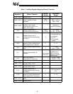
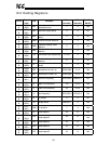
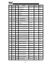
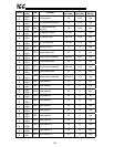
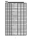
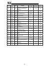
Sections 10.2 to 10.4 specify the communication number → holding register
mappings and coil definitions for all current VF-S7 communication numbers. Note
that the parameters and coils shown are those available at the time of this manual
printing; if new parameters are added by the drive manufacturer and/or parameter
adjustment limits are modified, etc., this will not affect the operation of the MDB-100
interface. As all available parameters, adjustment ranges etc. are determined solely
by the connected drive, and not the MDB-100, future drive firmware versions will
automatically be supported by the MDB-100 with no software upgrades required.
In the case of any discrepancies between the information in the following tables and
the drive’s documentation, the drive’s documentation should always be followed.
Some other important coil and holding register notes:
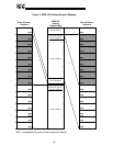
• Remember that all registers and coils indicated in the following sections are
shown with their “addressed as” coil & register numbers. These coil &
register numbers are 1 less than their “known as” numbers.
• A value indicated by “*” in the following tables indicates that the setting is
dependent on the connected drive’s capacity. Refer to the drive’s
documentation for these values.
• If frequency command values (registers 0x7A01 / 0xFA01) higher than each
respective drive’s FH or UL parameters are written, the write will be
acknowledged, but the drive will not change its frequency to this invalid value.
• All writes to holding registers use the drive’s RAM / EEPROM data write (“W”)
command except for registers 0x7A00 ∼ 0x7A02 and 0xFA00 ∼ 0xFA02,
which use the drive’s RAM data write (“P”) command.
• If an attempt is made to access non-existent registers or coils, an ILLEGAL
DATA ADDRESS exception (code 02) will be returned.
• If an attempt is made to write invalid data to a register or coil, an ILLEGAL
DATA VALUE exception (code 03) will be returned.
• If a drive connected to the MDB-100 goes “offline”, all coils will hold their last
state, with the exception of read-only coils #115 and/or #131, which will
indicate “offline”. Once communication with the drive(s) is reestablished,
these coil(s) will again indicate “online”.
• If a drive connected to the MDB-100 goes “offline”, attempts to access any
register in that drive’s register space will return a Modbus “SLAVE FAILURE”
error (code 04), except for the following registers, which will hold their last
state:
1. Communication command (communication number FA00)
2. Communication frequency command (communication number FA01)
3. Output frequency (communication number FD00)
4. Status (communication number FE01)
5. Output current (communication number FE03)
6. Output voltage (communication number FE05)
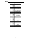
• Note that the MDB-100 does not assign drive register and coil functions; they
are entirely drive-dependent, and managed by the drive manufacturer.
• Each drive’s write-only coils are mapped to the corresponding drive’s
communication command parameter (communication number #FA00). Also,