


8
6. Repeat steps 1, 2, 4 and 5 above to connect another drive to Channel B on the
MDB-100, if desired.
7. Remove the cover of the MDB-100 by removing the 4 cover screws.
8. Configure the Modbus network characteristics such as baud rate, parity etc. via 8-
position DIP switch SW1 (refer to section 7). If the MDB-100’s station address is
to be configured locally, select the desired station address via 8-position DIP
switch SW2 (refer to section 8).
9. Reinstall the cover of the MDB-100.
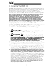
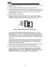
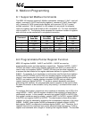
10. Connect the Modbus network cable (2 signal wires + shield) to the 3-position
pluggable terminal block marked “Network” on the left-hand side of the MDB-100.
The terminal ordering for the network cable wiring is as shown in Figure 1.
A
B
SHIELD
Figure 1: Modbus RS485 Network Terminal Wiring
Note that some RS485 equipment manufacturers reference the “A” and “B”
terminals reversed from the MDB-100’s hardware, and some manufacturers use
other labels, such as “+” and “-“. If you cannot communicate with the MDB-100
after installation, try switching the “A” and “B” signal wires - swapped signal wires
are the most common cause of communication difficulties in new RS485 network
installations.
Ensure that the Modbus network cable is tightly screwed into the terminals, and
route the cable such that it is located well away from any drive input power or
motor wiring. Also take care to route all cables away from any sharp edges or
positions where they may be pinched.
11. Take a moment to verify that the MDB-100 and all network cables have sufficient
clearance from drives, motors, and power-carrying electrical wiring.
12. Turn the power sources to all connected drives ON, and verify that the drives
function properly. If the drives do not appear to power up, or do not function
properly, immediately turn power OFF.
Repeat steps 1 and 2 to remove all
power from the drives.
Then, verify all connections. Contact ICC or your local
drive distributor or manufacturer for assistance if the problem persists.