


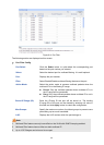
Step Operation Description
3 Configure parameters for
multicast VLAN
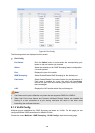
Optional. Enable and configure a multicast VLAN on the
Multicast→IGMP Snooping→Multicast VLAN page.
It is recommended to keep the default time parameters.
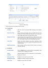
4 Look over the configuration If it is successfully configured, the VLAN ID of the multicast
VLAN will be displayed in the IGMP Snooping Status table
on the Multicast→IGMP Snooping→Snooping Config
page.
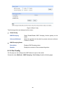
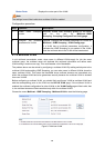
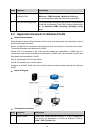
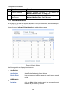
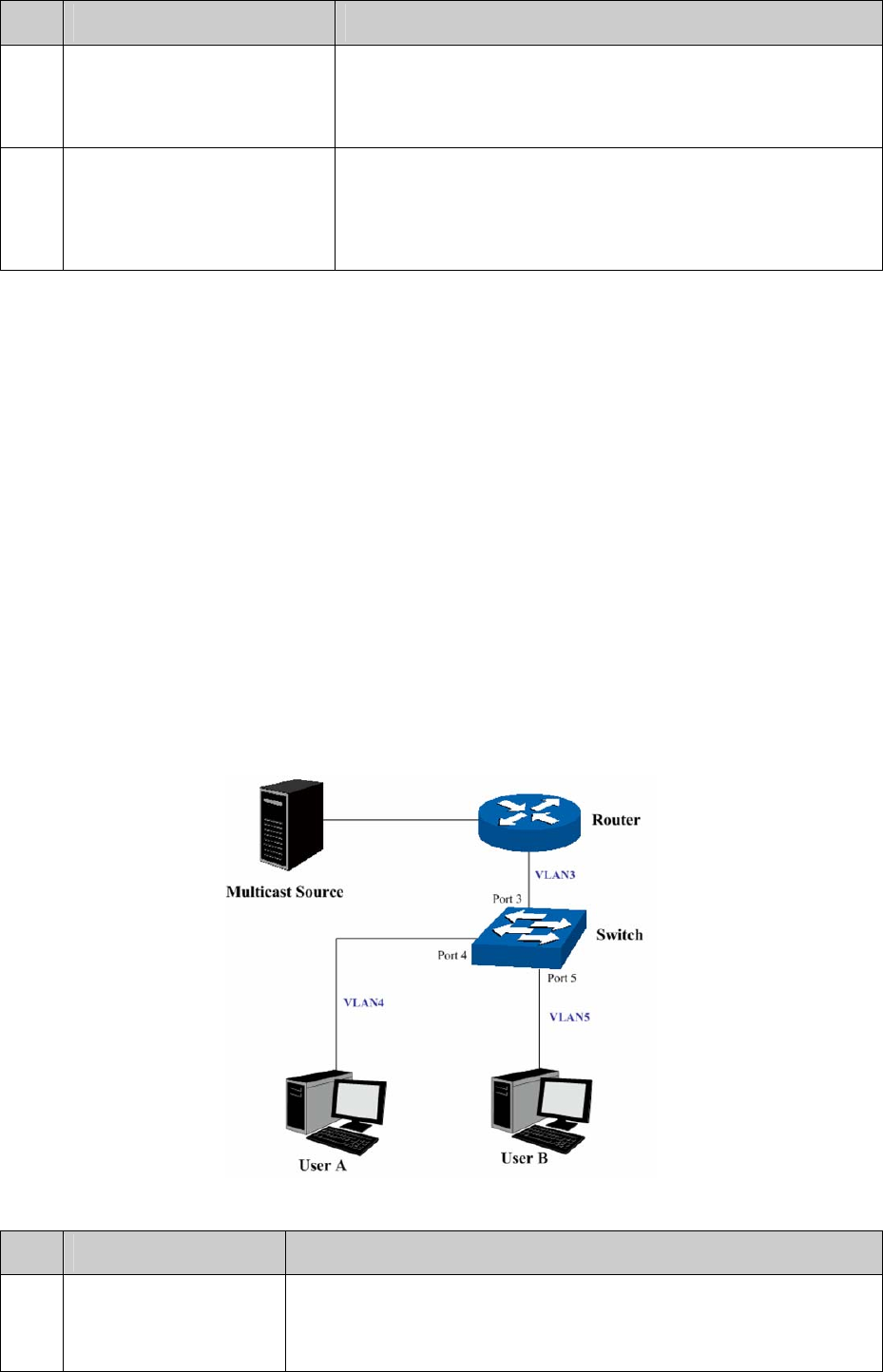
8.2 Application Example for Multicast VLAN
Network Requirements
Multicast source sends multicast streams via the router, and the streams are transmitted to user A
and user B through the switch.
Router: Its WAN port is connected to the multicast source; its LAN port is connected to the switch.
The multicast packets are transmitted in VLAN3.
Switch: Port 3 is connected to the router and the packets are transmitted in VLAN3; port 4 is
connected to user A and the packets are transmitted in VLAN4; port 5 is connected to user B and
the packets are transmitted in VLAN5.
User A: Connected to Port 4 of the switch.
User B: Connected to port 5 of the switch.
Configure a multicast VLAN, and user A and B receive multicast streams through the multicast
VLAN.
Network Diagram
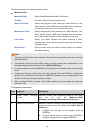
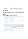
Configuration Procedure
Step Operation Description
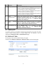
1 Create VLANs Create three VLANs with the VLAN ID 3, 4 and 5 respectively,
and specify the description of VLAN3 as Multicast VLAN on
VLAN→802.1Q VLAN page.
11
0