


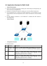
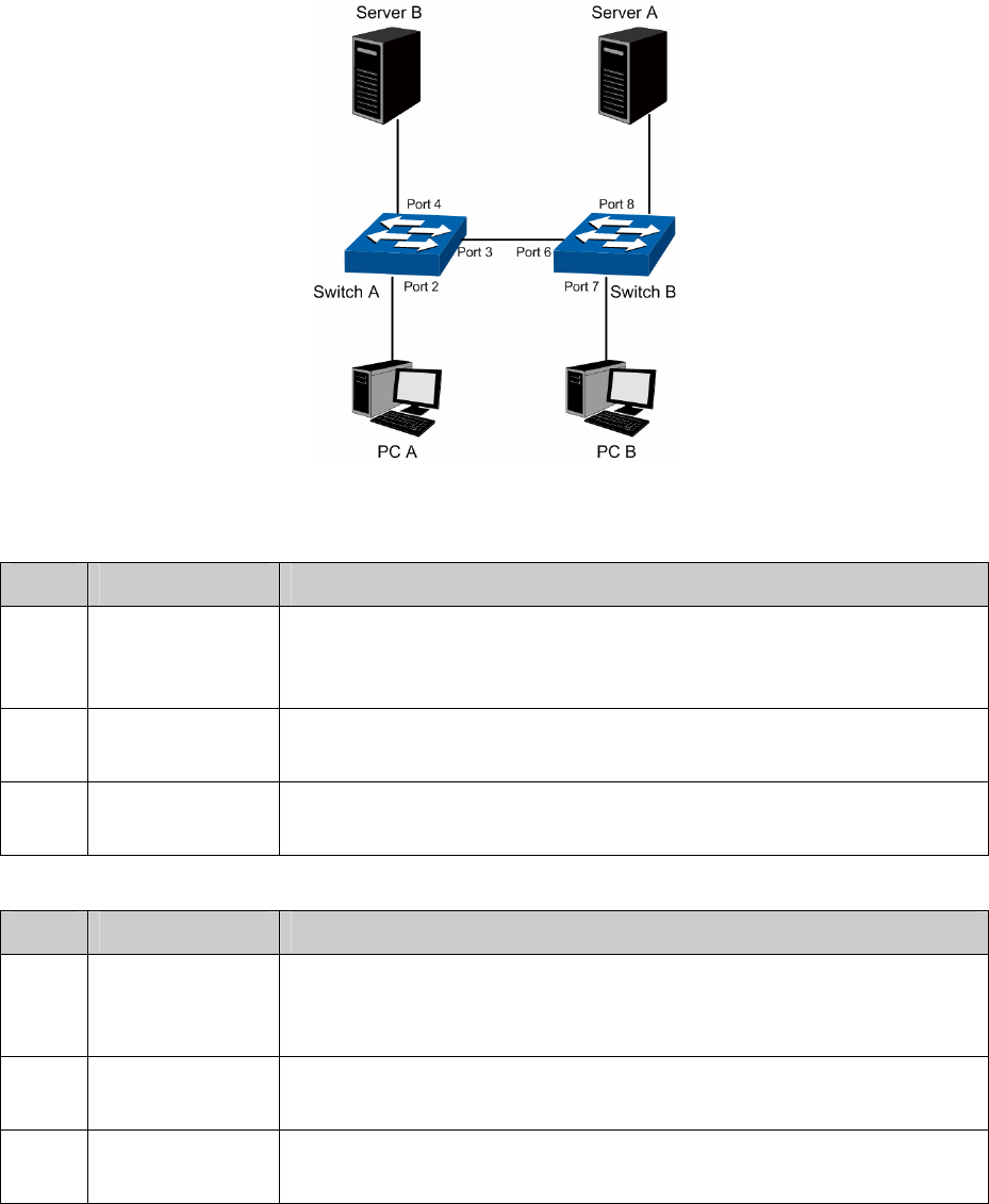
Switch B is connecting to PC B and Server A;
PC A and Server A is in the same VLAN;
PC B and Server B is in the same VLAN;
PCs in the two VLANs cannot communicate with each other.
Network Diagram
Configuration Procedure
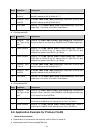
Configure switch A
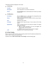
Step Operation Description
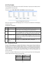
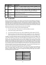
1 Configure the
Link Type of the
ports
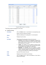
Required. On VLAN→802.1Q VLAN→Port Config page, configure
the link type of Port 2, Port 3 and Port 4 as ACCESS, TRUNK and
ACCESS respectively
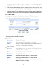
2 Create VLAN10 Required. On VLAN→802.1Q VLAN→VLAN Config page, create a
VLAN with its VLAN ID as 10, owning Port 2 and Port 3.
3 Create VLAN20 Required. On VLAN→802.1Q VLAN→VLAN Config page, create a
VLAN with its VLAN ID as 20, owning Port 3 and Port 4.
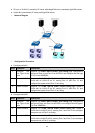
Configure switch B
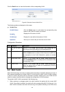
Step Operation Description
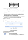
1 Configure the
Link Type of the
ports
Required. On VLAN→802.1Q VLAN→Port Config page, configure
the link type of Port 7, Port 6 and Port 8 as ACCESS, TRUNK and
ACCESS respectively.
2 Create VLAN10 Required. On VLAN→802.1Q VLAN→VLAN Config page, create a
VLAN with its VLAN ID as 10, owning Port 6 and Port 8.
3 Create VLAN20 Required. On VLAN→802.1Q VLAN→VLAN Config page, create a
VLAN with its VLAN ID as 20, owning Port 6 and Port 7.
62