


CAUTION: This device should only be operated with the type of power source
indicated on the instrument nameplate. If you are not sure of the type of power
service available, please consult your local power company.
4.1.1. AC Powered Units
Plug the supplied power cable into the receptacle on the CMS back panel and then connect the
power cable to a grounded AC outlet. The AC powered version of the CMS features a self
adjusting power supply that automatically adapts to power supplies between 90 and 250 VAC.
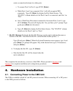
4.1.2. DC Powered Units
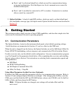
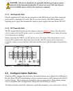
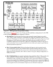
The DC terminal block features two bus inputs as shown in Figure 4.1 below. This allows the
user to connect only one DC power source, or connect two DC power sources where the second
source functions as a backup.
When connecting the CMS to your DC power source, first remove the clear protective cover
from the DC terminal block, attach the wires from the -48V DC power source to the screw
terminals, connect your ground line to the labeled ground screw, and then replace the protective
cover.
Figure 4.1: Terminal Block Assembly (DC Units Only)
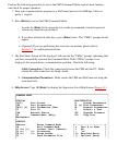
4.2. Configure Option Switches
When the CMS is shipped from the factory, the Option Switches are configured for 9600 baud, 8
Bits-No Parity, RTS/CTS handshaking, verbose command response, and command echo ON (all
switches Down). These settings are compatible with most applications. If the default settings
are not compatible with your application, change the switch settings as follows.
The Option Switches should be configured to match the parameters your control device will use