


Inverter/Charger Installation
2–4 975-0239-01-01
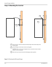
Step 1: Installing the Mounting Plate
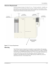
Each XW Inverter/Charger and XW Power Distribution Panel requires a separate
mounting plate. This bracket is first attached to the wall, then the inverter/charger or
distribution panel is attached to the wall bracket.
The wall bracket is attached to the wall with lag bolts or other fasteners, provided by the
installer. A minimum of four ¼-inch diameter fasteners are required. The fasteners must
be sufficiently strong to support 500 pounds.
The wall bracket has mounting holes spaced 16 inches (40 cm) apart and is designed to
span two wall studs spaced 16 inches on-center. Additional mounting holes are also
provided for flexibility in mounting options. If the wall does not have 16-inch on-center
studs, the installer will need to provide adequate supports for the brackets. For example, a
sheet of plywood can be attached to the wall, and the wall brackets can then be attached to
plywood.
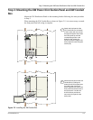
Both the XW Inverter/Charger and XW Power Distribution Panel use the same wall
bracket. The brackets are designed to interlock (as shown in Figure 2-3), so that additional
mounting plates are easily installed without additional measuring or levelling.
The type of fastener required to secure the mounting plate varies according to the vertical
surface and wall structure of your installation location.
Table 2-1
Mounting Plate Fastener Recommendations
Structure Required Fastener
Number of Screws
Per Bracket
Wood studs at 16" (on center - O.C.) 1/4" Ø × 3 1/2" long lag screw Four
Wood studs not at 16" O.C. (3/4" minimum
plywood panel required)
1/4" Ø × 1" long wood screw Six
Steel studs at 16" O.C. (minimum 18 gauge) 1/4" Ø self-drilling screw Four
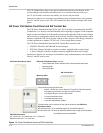
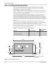
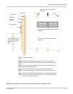
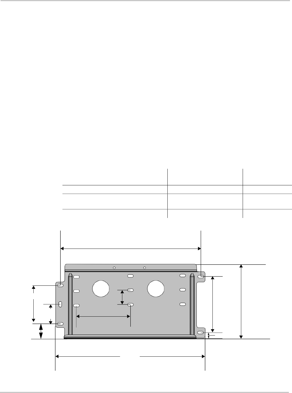
Figure 2-2
Mounting Plate Dimensions
17 (432)
9 3/16
(233)
6 7/8
(175)
1 3/4 (45)
6 (153)
2 1/4
(57)
4 1/2 (115)
16 (406)
all measurements in inches
(millimeters)
3/4 (19)
2 (49)