


Mounting
975-0239-01-01 4–5
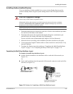
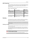
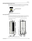
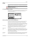
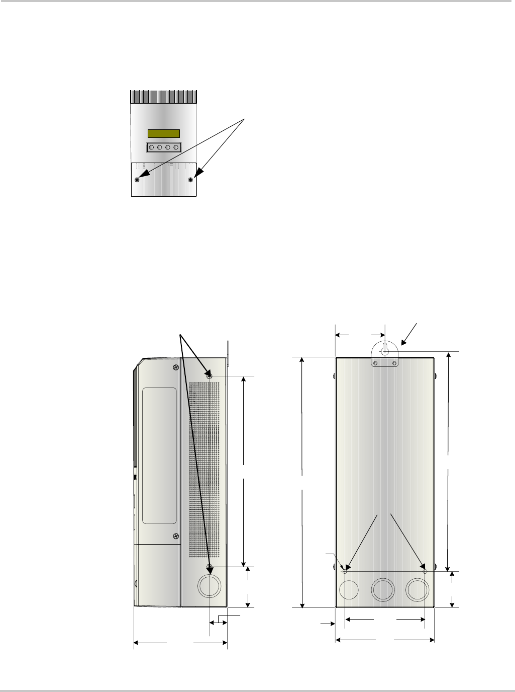
Removing the Wiring Terminals Cover
Before mounting, you must remove the wiring terminals cover to access the mounting
holes and the wiring terminals. The wiring terminals cover is secured with two Phillips
#8-32 × 2 ½-inch screws on the front cover of the unit. See Figure 4-2.
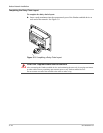
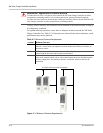
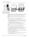
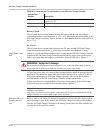
Removing Knockouts
Six dual and two single knockouts are provided for routing battery, PV array, BTS, and
network cables into the XW Solar Charge Controller. Bushings or conduits must be used
to protect the wiring from damage from rough edges around the knockout holes.
Figure 4-2
Removing the Wiring Terminals Cover
Remove screws to access
the field-wiring terminals.
xantrex
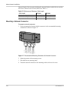
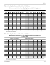
Figure 4-3
Dimensions and Knockout Locations
1"
(25.4 mm)
2 7/8"
(73 mm)
1
4
½
"
(
3
6
8
m
m
)
1
2
¾
"
(
3
2
3
m
m
)
9/16"
(14 mm)
¼"
(6.35 mm)
4 5/8"
(118 mm)
5 ¾"
(146 mm)
2 1/16"
(53 mm)
2 3/8"
(60 mm)
11"
(280 mm)
5 7/16"
(138 mm)
Keyhole slot for wall mounting
Additional
mounting holes
Side screws for power distribution
panel mounting