


The XW System Control Panel
975-0239-01-01 5–3
Materials and Tools Required
You will need these materials and tools to complete the installation:
❐ Mounting template sticker (supplied)
❐ Mounting plate (supplied)
❐ mounting plate (supplied)
❐ Four #6 screws (supplied)
❐ Two #8 screws (supplied)
❐ Cable clamps or hardware fasteners
❐ Xantrex network cables or equivalent (CAT 5 or CAT 5E cable with RJ45 connectors
wired to T568A standard) A 7-foot cable is provided.
❐ Xantrex male network terminator (supplied).
❐ Phillips head screwdriver
❐ Jigsaw or small keyhole saw
❐ Power drill with 1/8" bit (optional)
Choosing a Location
Choose a location that is easily accessible. The XW System Control Panel should be
mounted where you can have unobstructed access to the screen and buttons.
The location should be indoors, dry, and free from corrosive or explosive fumes.
Mounting the XW System Control Panel
The XW System Control Panel can be mounted three ways:
• Flush mounted through an opening in a wall using the mounting plate
• Surface mounted using the mounting plate
• Flush mounted through an opening in a wall and secured with four #6 screws.
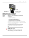
To flush mount the XW System Control Panel with mounting plate:
1. Using a jigsaw and the supplied template sticker as a guide, cut out the hole for the
mounting plate. The mounting plate fastens to walls up to 3/4 inch (19 mm) thick.
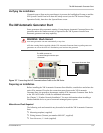
2. Route the network cable from the GT Inverter inside the wall and through the opening.
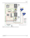
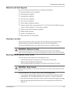
3. Insert the mounting plate with the two tabs in a vertical position into the hole (see
Figure 5-2).
WARNING: Explosion hazard
The XW System Control Panel is not Ignition Protected. Do not install in areas requiring
Ignition-Protected equipment, such as areas containing gasoline engines, tanks, or fuel-line fittings.
WARNING: Shock hazard
Before making an opening in a wall or panel, ensure there is no wiring or other obstruction within
the wall.