


5
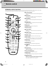
Controls and functions
3
HDMI
G/Y B/PB/CB R/PR/CR
INPUT A
HD/SYNC
VD
OUT IN
REMOTE
TRIGGER OUT
S VIDEO VIDEO
INPUT B
RGB/YP
BPR/YCBCR
RS-232C
D4 VIDEO
q
8
765432190
wer
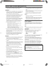
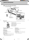
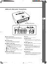
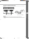
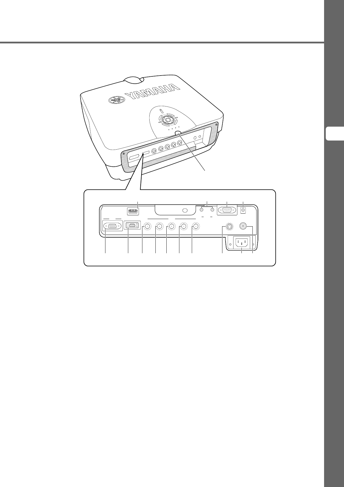
◆Main unit <Rear panel / Connections>
1 INPUT B (D-sub 15 pin)
Receives component video and RGB (RGB/YPBPR/YCBCR)
signals. Use a D-sub monitor cable to connect components to
this jack.
2 D4 VIDEO (D jack)
Receives signals output from the D jacks of other AV
components. It is compatible with D1 - D4 formats.
3 - 7 INPUT A (BNC jacks)
Receive component video and RGB signals. Connect
component signal connectors from AV components to input
jacks 3 - 5, and RGB signal connectors from computers to
input jacks 3 - 7. Use BNC cables for these connections.
3 G/Y (G, or luminance signal)
4 B/P
B/CB (B, or color difference signal)
5 R/P
R/CR (R, or color difference signal)
6 HD/SYNC (Horizontal sync signal, composite sync signal)
7 VD (Vertical sync signal)
8 S VIDEO (Mini DIN jack)
Receives signals from S-VIDEO output jacks of other AV
components. Use an S-VIDEO cable for these connections.
9 AC inlet
Insert the supplied AC power cable here.
0 VIDEO (Pin Jack)
Receives composite video signals from the VIDEO output
jacks of other AV components. Use a video pin cable for these
connections.
q HDMI
TM
(HDMI
TM
jack)
Receives HDMI
TM
signals from computers or AV components.
w REMOTE IN / OUT jack
Connect the remote control to the REMOTE IN jack if you
want to use it through a cable. The REMOTE OUT jack
outputs the signal received through the REMOTE IN jack
without any change.
e RS-232C (D-sub 9 pin)
For use in servicing this unit.
r TRIGGER OUT
Outputs control signals to external components. This output
provides a potential of 12 V/ maximum 200 mA when this unit
is projecting. Use the supplied trigger-out DC plug (for US
model only) to control external components.
Rear remote control sensor
11_DPX-1100_E.p65 2004.04.16, 12:555