


About VLANs C-7
Overlapped IP
VLANs
The CoreBuilder system also gives you the ability to assign network
layer information to IP VLANs. This capability allows network
administrators to manage their VLANs by subnetwork. Flooding
decisions are made by first matching the incoming frame using the
protocol (IP) and then matching it with layer 3 subnetwork information.
If received data is IP but does not match any defined IP subnetwork
VLAN, it is flooded within all IP VLANs using the relevant switch port.
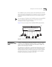
For example, two IP VLANs can be configured for ports 1-10 as follows:
IP VLAN 1 - subnet 158.101.112.0, ports 1-10
IP VLAN 2 - subnet 158.101.113.0, ports 1-10
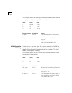
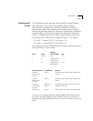
This example shows how flooding decisions are made using overlapping IP
VLANs (assuming a 12-port switch):
As shown in this example, when the subnet address of an IP packet does
not match any subnet address of any defined IP VLAN in the system, it is
flooded to all of the IP VLANs that share the source switch port, in this case,
port 6.
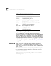
Index VLAN
Network
Address/Mask
Ports
1 Default none 1 - 12
2 IP 158.103.122.0/
255.255.255.0
1 - 6
3 IP 158.103.123.0/
255.255.255.0
6 - 12
Data received on Is flooded on Because
IP subnet
158.103.122.2
on port 6
VLAN 2 IP network layer matches layer 3 address for
VLAN 2.
IP subnet
158.103.123.2
on port 6
VLAN 3 IP network layer matches layer 3 address for
VLAN 3.
IP subnet
158.103.124.2
on port 6
VLAN 2 and
VLAN 3
IP network layer does not match any layer 3
address for IP VLANs.
IPX on port 6 VLAN 1 IPX frame does not match any defined VLAN.