


14 CHAPTER 2: INTRODUCING THE ROUTER 6000 FAMILY
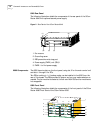
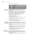
Table 4 RPU LED and button description
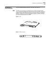
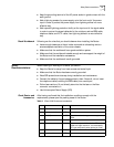
Interface Console interface
Table 5 Console interface attributes
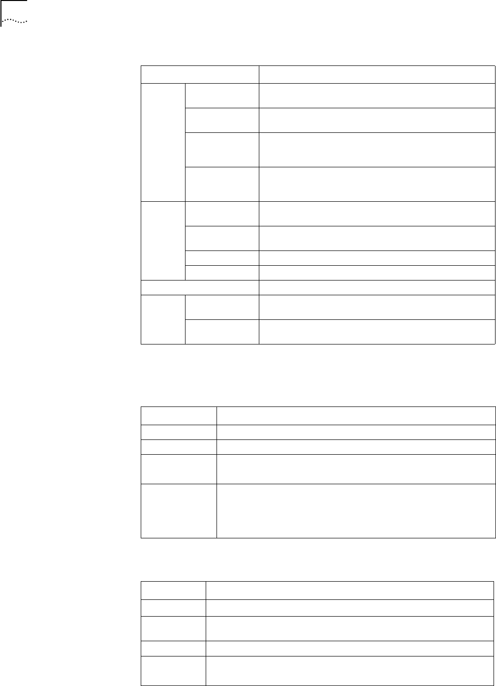
AUX interface
Table 6 AUX interface attributes
LED and button Description
RUN
(green)
RPU System operation LED. Blinking means the CPU is in normal
operation, constant ON or OFF means the CPU has failed.
FAN FAN operation LED. Constant ON means the FAN is operating
normally.
PWR1 PWR1 operation LED. Constant ON means PWR1 is operating
normally, and constant OFF means PWR1 is no in place or has
failed.
PWR2 PWR2 operation LED. Constant ON means PWR2 is operating
normally, and constant OFF means PWR2 is no in place or has
failed.
ALM (red) RPU System failure LED. ON means CPU has received an alarm
signal for PWR or FAN (due to overheating, for example).
FAN FAN failure LED. ON means the FAN is no in place or its
rotation is obstructed.
PWR1 PWR1 failure LED. ON means PWR1 has failed.
PWR2 PWR2 failure LED. ON means PWR2 has failed.
RESET RPU hardware reset button.
10/100BA
SE-TX LED
LINK (green) OFF means the link is not connected and ON means the link
is connected.
ACT (yellow) OFF means no data is being transceived on the interface and
blinking means data is being transceived.
Attribute Description
Connector RJ45
Interface standard RS232
Baud rate 9600bps ~ 115200bps
9600bps by default
Supported service Connect to the ASCII terminal
Connect to the serial interface of the local PC and run terminal
emulation program on the PC
Command Line Interface (CLI)
Attribute Description
Connector RJ45
Interface
standard
RS232
Baud rate 300 ~ 115200bps
Supported
service
Modem dialup
Backup