


6
HARDWARE MAINTENANCE
Hardware
Maintenance
Please review the following cautions before installation or maintenance.
1) On a mounting screw of 3Com 6000 series router chassis, there is an
anti-dismantle seal of 3Com Corporation. The seal must be kept intact before the
support agent performs maintenance on the switch.
2) Remember to wear ESD-preventive wrist strap.
Power Module
Removal and
Installation
6000 Series Routers support 1+1 redundant power system. The power
modules are hot-swappable.
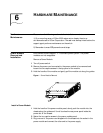
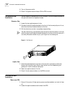
Remove a Power Module
1 Turn off power switch.
2 Remove the power cord connected to the power module to be removed and
loosen the two captive screws in the top panel of the module.
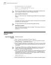
3 Hold the handle of the module and gently pull the module out along the guides.
Figure 1 Power Module Removal
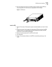
Install a Power Module
1 Hold the handle of the power module panel, slowly push the module into the
chassis along the guides until it well touches the rear power panel inside the
power slot of the chassis.
2 Fasten the two captive screws in the power module panel.
3 Plug one end of the power cord shipped with the chassis into the socket in the
power module and connect the other end to the power supply.