


62 CHAPTER 8: FLEXIBLE INTERFACE CARDS
Connect Interface
Optical Fiber
CAUTION: When connecting optical fiber, please note:
■ Do not bend optical fiber with excessive stress. The bend radius should be no
less than 10 cm.
■ Ensure that the Tx terminal and the Rx terminal of the interface are connected
correctly.
■ Keep the sectional surface of optical fiber clean and free from dust.
WARNING: Laser Danger! Do not observe the optical fiber connector connected
with the laser in case the invisible laser radiation harms your eyes.
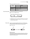
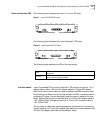
1 Find the Rx optical port and Tx optical ports on 100 FX MM/100 FX SM. Insert one
end of an optical fiber into the Rx optical port of 100 FX MM/100 FX SM, and the
other end into the Tx optical port of the peer device; insert one end of another
optical fiber into the Tx optical port of 100 FX MM/100 FX SM, and the other end
into the Rx optical port of the peer device.
2 Power on the Router and check the status of the LINK LED on the
100BASE-MM/100BASE-F SM panel. ON means the Rx link has been connected
and OFF means the Rx link is not connected. In the latter case, check the line.
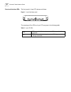
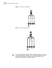
4-port Enhanced Serial
FIC (3C13863)
8-port Enhanced Serial
FIC (3C13864)
4-port / 8-port FIC stands for 4-/8-port enhanced high-speed sync/async serial
interface card. The cards functions mainly to transmit, receive, and process the
data on the synchronous/asynchronous serial interface. They support both
synchronous and asynchronous modes. In the former case, they support the
DTE/DCE mode.
Introduction to DTE and
DCE
A card is usually connected to an external modem for the dialing purpose. In this
case, an appropriate baud rate must be set.
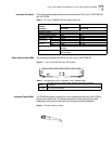
The synchronous serial interface can work in either DTE or DCE mode. Two devices
directly connected should work as DTE and DCE respectively. The DCE device
provides the synchronization clock and specifies communication rate, and the DTE
device accepts the synchronization clock and communicates at the specified rate.
The Router normally works as a DTE. To know whether the specific equipment
connected with the Router is DTE or DCE, please refer to the manual shipped with
the equipment.
Speed and transmission
distance of
synchronous/asynchron
ous serial interface
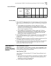
In different operating modes, the synchronous/asynchronous serial interface
supports different electric signal specifications and baud rates. In addition, the
maximum signal transmission distance not only depends on the specified baud
rate but also the selected cable. The following table shows how the cable type,
baud rate, and the maximum signal transmission distance related to each other.
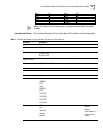
Table 4 Speed and transmission distance of V.24 (RS232)/V.35/X.21 cable
V.24 (RS232) V.35/X.21
Baud rate (bps)
Max. transmission
distance (m) Baud rate (bps)
Max. transmission distance
(m)
2400 60 2400 1250