


26 CHAPTER 3: INSTALLING THE ROUTER
strap, and connect the other end of the cable to the AC outlet that provides
power supply.
3 Check that the POWER LED on the front panel of the Router is ON, which means
the power cord connection is correct.
Connecting the Console
Terminal
Each 6000 Router provides an RS232-compliant asynchronous serial console port
(CON), through which the user can configure the Router.
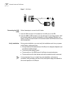
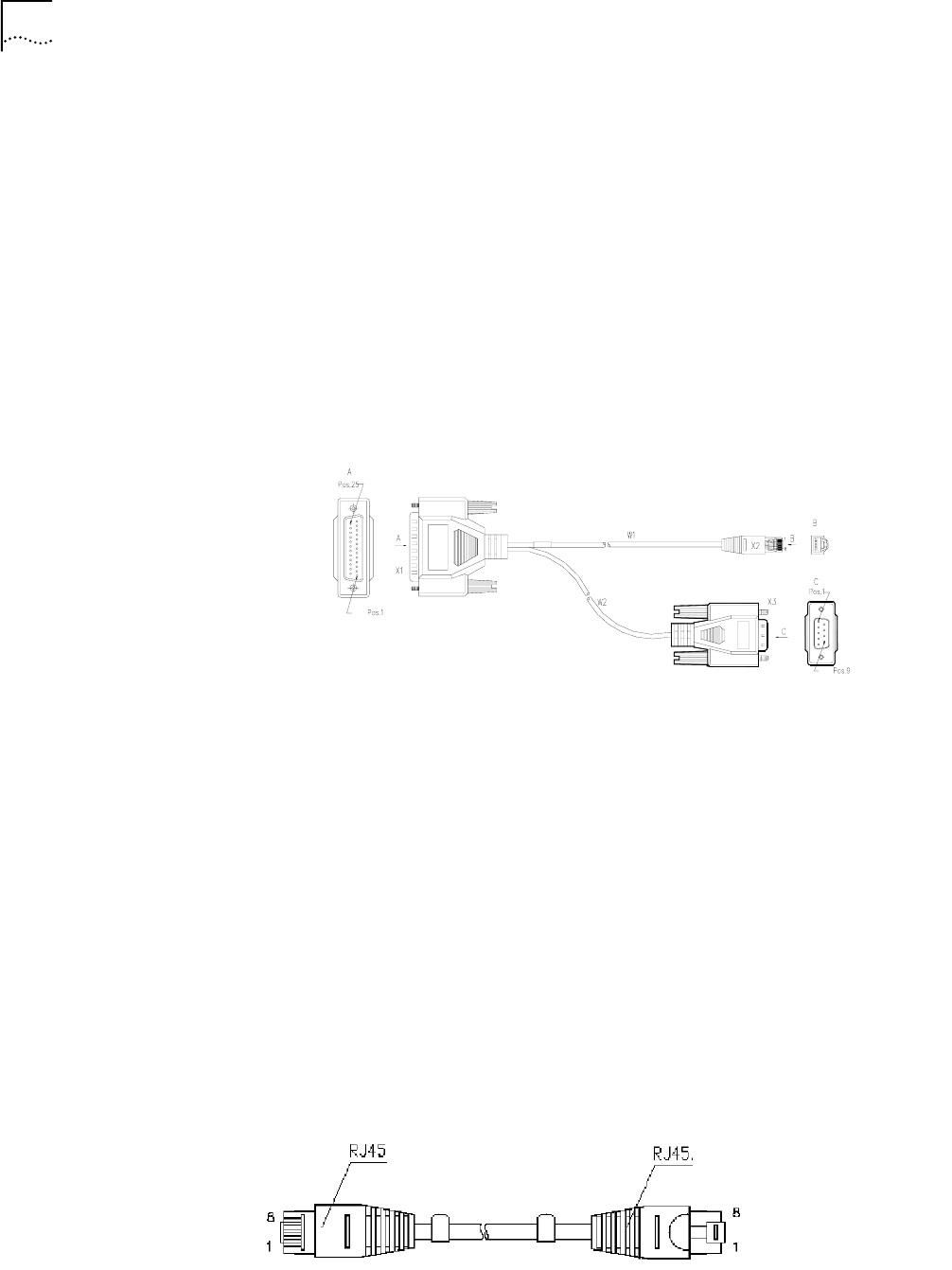
Console cable
Console cable is an 8-core shielded cable. At one end of the cable is a crimped
RJ45 connector that plugs into the console port of the Router. At the other end of
the cable is a DB9 (female) connector and a DB25 (female) connector.
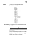
Figure 6 Console Cable
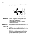
Connect console cable
Before you can configure the Router at the console terminal, connect the console
cable in the following steps:
1 Select a console terminal. Console terminal can be a standard ASCII terminal
possessing an RS232 serial port, or a regular PC, but the latter is often used.
2 Connect the cable. Power off the Router and console terminal, and connect the
RS232 serial port to the console port on the RPU via a console cable.
3 Power on the Router after verifying the installation. If the Router is working
normally, the system will display the router boot information on the console
terminal.
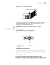
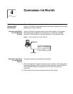
Connecting Router to
LAN
6000 Routers provide the fixed 10/100BASE-TX interface. 10/100BASE-TX
Ethernet interface uses the category 5 twisted-pair for connection, as shown in
the following figure.
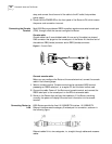
Ethernet cables fit into two categories, i.e., straight-through cables and crossover
cables.