


4-port Enhanced Serial FIC (3C13863) 8-port Enhanced Serial FIC (3C13864) 65
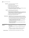
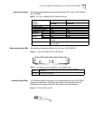
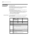
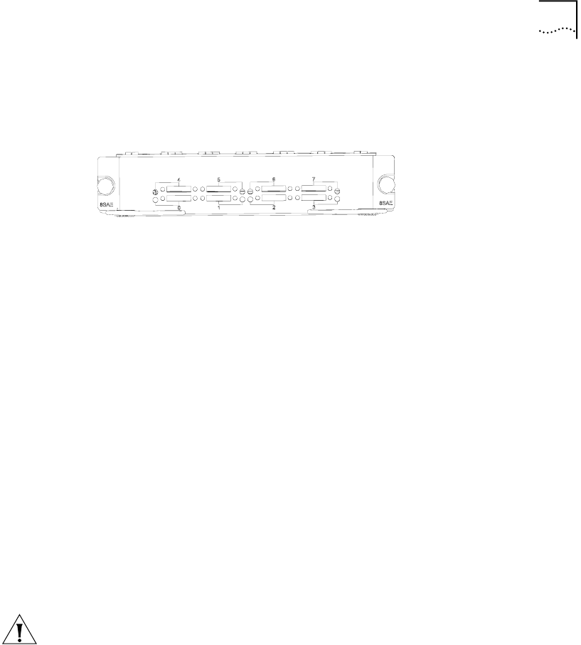
The front panel of 8-port FIC is shown as follows:
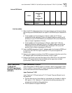
Figure 6 8-port FIC front panel
On 8-port FIC, each link corresponds to a LED. ON means the link is connected.
Blinking means data is being transceived.
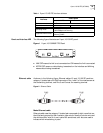
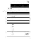
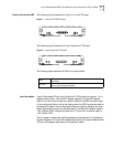
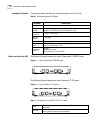
Interface Cable The FIC uses sync/async serial interface cable with DB28 connector. V.24 (RS232)
DTE cable: DB25 (male) connector at the network end
■ V.24 (RS232) DCE cable: DB25 (female) connector at the network end
■ V.35 DTE cable: 34PIN (male) connector at the network end
■ V.35 DCE cable: 34PIN (female) connector at the network end
■ X.21 DTE cable: DB15 (male) connector at the network end
■ X.21 DCE cable: DB15 (female) connector at the network end
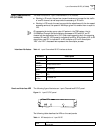
One end of the cables is connected to the router side via the DB-28 connector, and
the connection of the other end of the cables varies with the network side to
which it is connected.
Connecting the Interface
Cable
CAUTION:Before connecting the FIC, confirm the model of the equipment that is
connected with the signaling criterion required by the access equipment, baud
rate, and synchronous clock.
1 Check interface type of the peer device and choose the sync/async serial interface
cable of correct type.
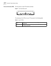
2 Plug the DB-28 end of the connection cable to the corresponding DB-28 interface
in the FIC.
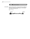
3 Connect the other end of the FIC cable to the following equipment:
If the WAN is a DDN, please connect the cable to the interface of the CSU/DSU.
If the WAN is a dialup line, please connect the cable to the serial interface of the
analog Modem.
4 Power on the router, and check the status of the LINK LED of the FIC. It is off when
the line is faulty and signal is out of step.