3-18 Machine Maintenance Procedures
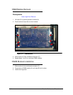
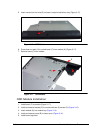
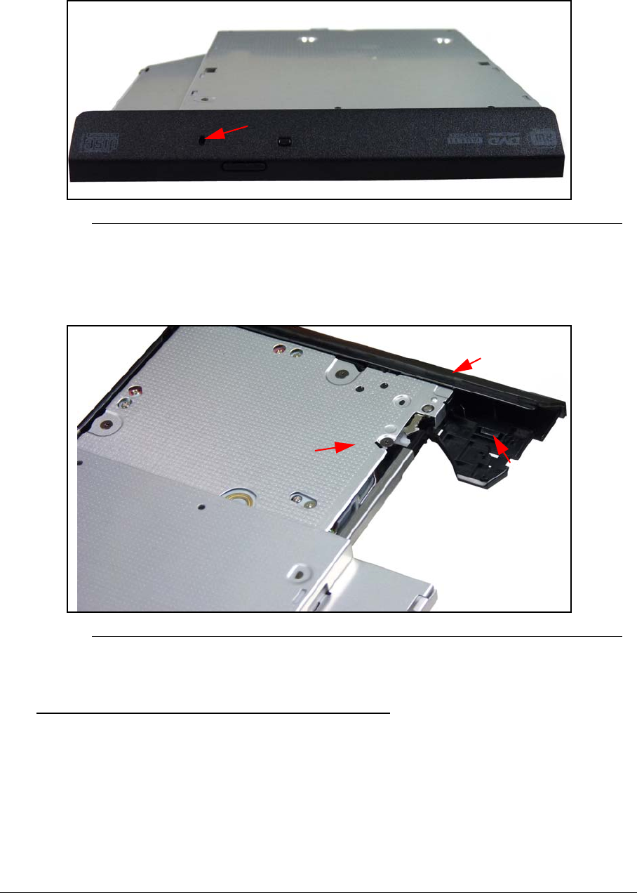
5. Insert narrow tool into hole (G) on bezel, to eject module from tray (Figure 3-17).
Figure 3-16. ODD Module
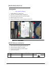
6. Press down on latch (H) to unlock bezel (F) from module (A) (Figure 3-17).
7. Remove bezel (F) from module.
Figure 3-17. ODD Module
ODD Module Installation 0
1. Install bezel (F) to module (Figure 3-17).
2. Install and secure bracket (E) to module with two (2) screws (D) (Figure 3-15).
3. Insert module (A) into module bay (Figure 3-14).
4. Install and secure screw (B) to lower cover (Figure 3-14).
5. Install lower logic door.
G
A
H
F


