


3-22 Machine Maintenance Procedures
Upper Cover Removal 0
Prerequisite:
HDD Module Removal
Keyboard Removal
DIMM Module Removal
WLAN Module Removal
Optical Disk Drive (ODD) Module Removal
NOTE:
NOTE:
WLAN cables shown in the following images may not reflect the final product.
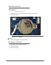
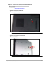
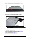
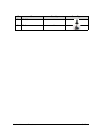
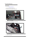
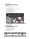
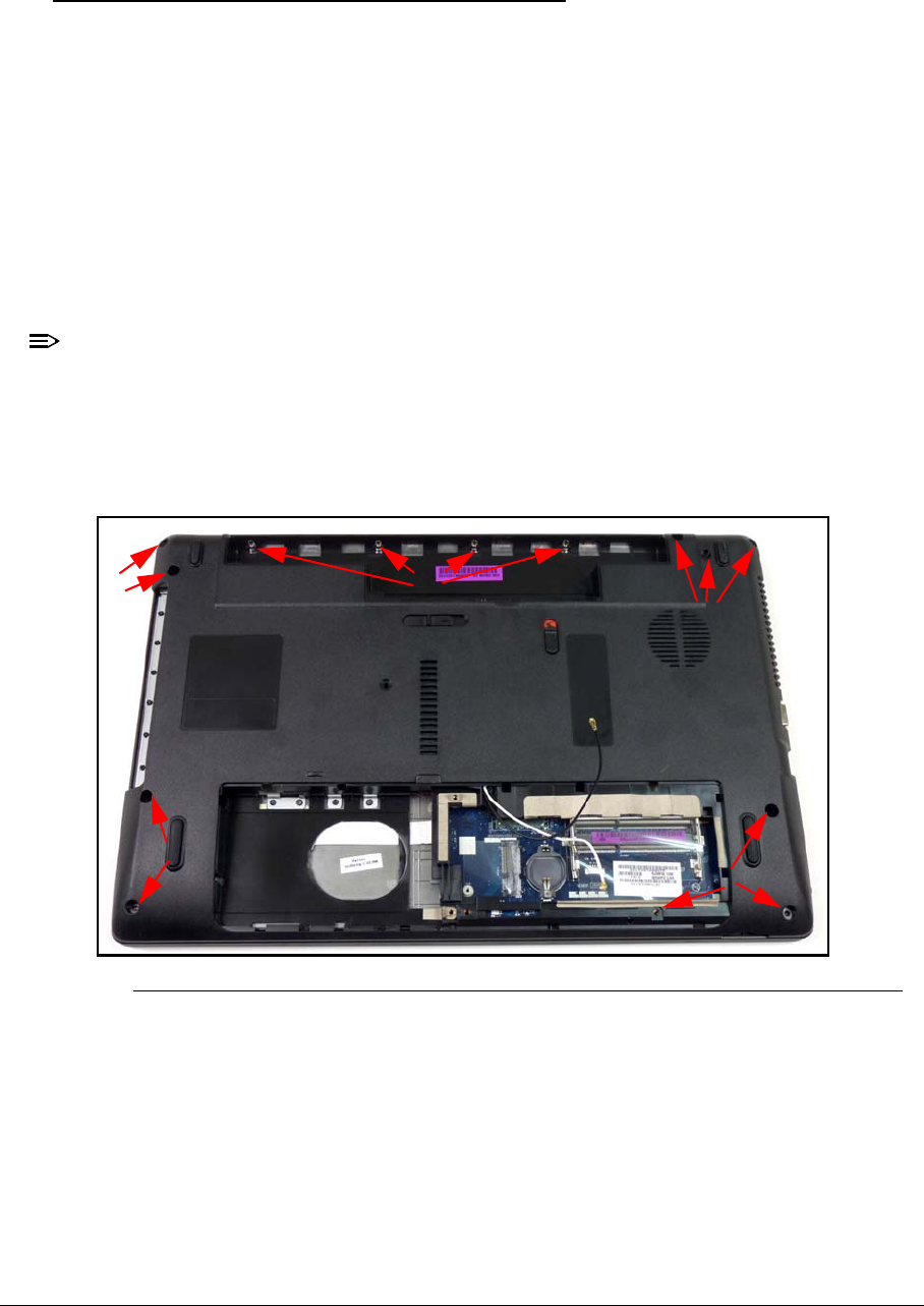
1. Remove the following screws:
ten (10) screws (A) from lower cover
four (4) screws (B) from battery bay.
Figure 3-22. Lower Cover
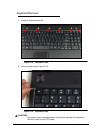
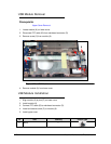
2. Place computer on surface, face up.
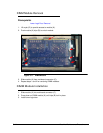
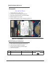
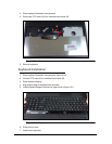
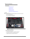
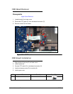
3. Disconnect the following cables:
power board FFC cable (C) from mainboard connector (D)
touchpad FFC cable (E) from mainboard connector (F)
speaker cable (G) from mainboard connector (H).
A
B
A
A
A