


PRELIMINARY Appendix A: Specifications and Data
Megabit Modem 500L Installation Manual 67
PR
EL
I
M
I
N
A
RY
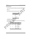
Connector Pinouts
You can make your own cables for the ADSL RJ-11 connector and the 10/100BASE-T Ethernet
connector on the rear of the modem. The following sections provide the pinout information.
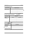
ADSL Port
The following table shows the signal on each pin for the ADSL port. The connector for this
interface is an RJ-11. See page 14 for the location of this port.
10/100BASE-T Port
The following table shows the signal on each pin when the switch is in either the MDI or
the MDI-X position for the 10/100BASE-T port. The connector for this interface is an RJ-45.
See page 14 for the location of this port.
Pin Signal
1 Not used
2 No connection
3 Ring
4 Tip
5 No connection
6 Not used
MDI MDI-X Signal Description
1 3 TX+ Transmit Data (+)
2 6 TX- Transmit Data (-)
3 1 RD+ Receive Data (+)
4 4 Not used Not used
5 5 Not used Not used
6 2 RD- Receive Data (-)
7 7 Not used Not used
8 8 Not used Not used